

Rear axle steering system for a mobile crane
- Summary
- Abstract
- Description
- Claims
- Application Information
AI Technical Summary
Benefits of technology
Problems solved by technology
Method used
Image

Examples
first embodiment
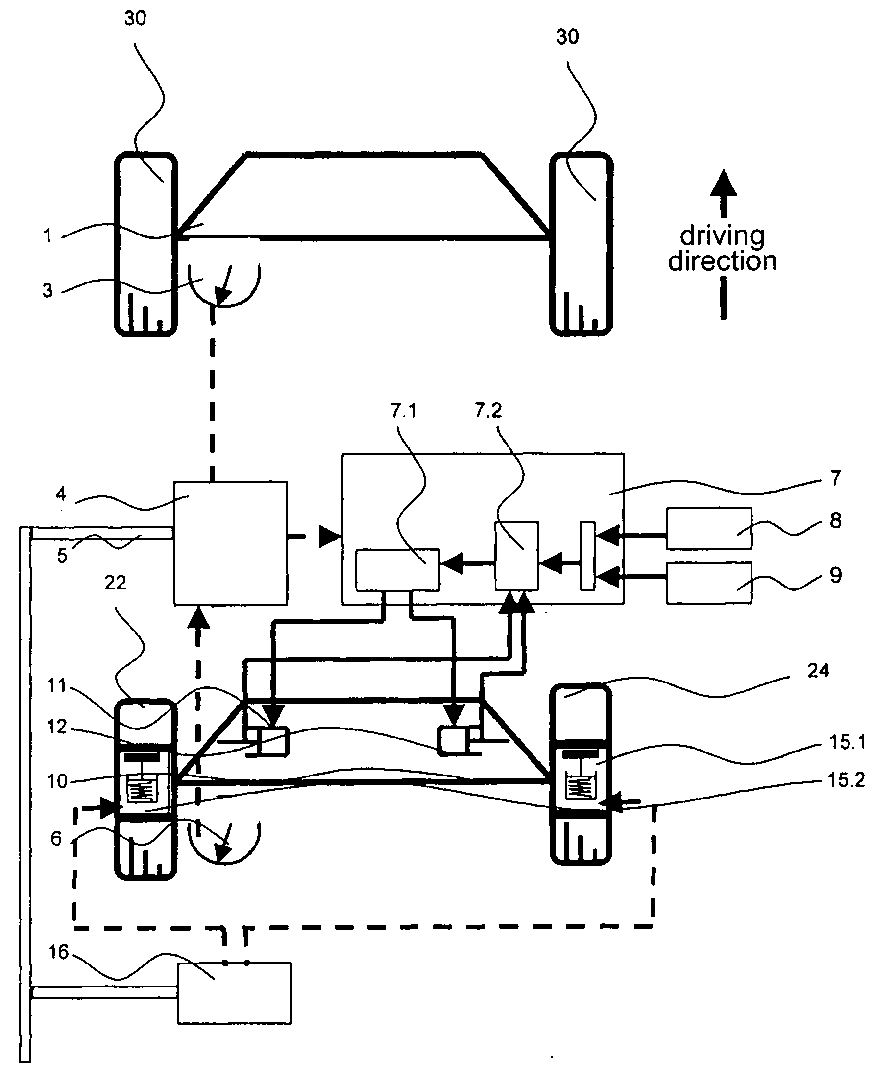
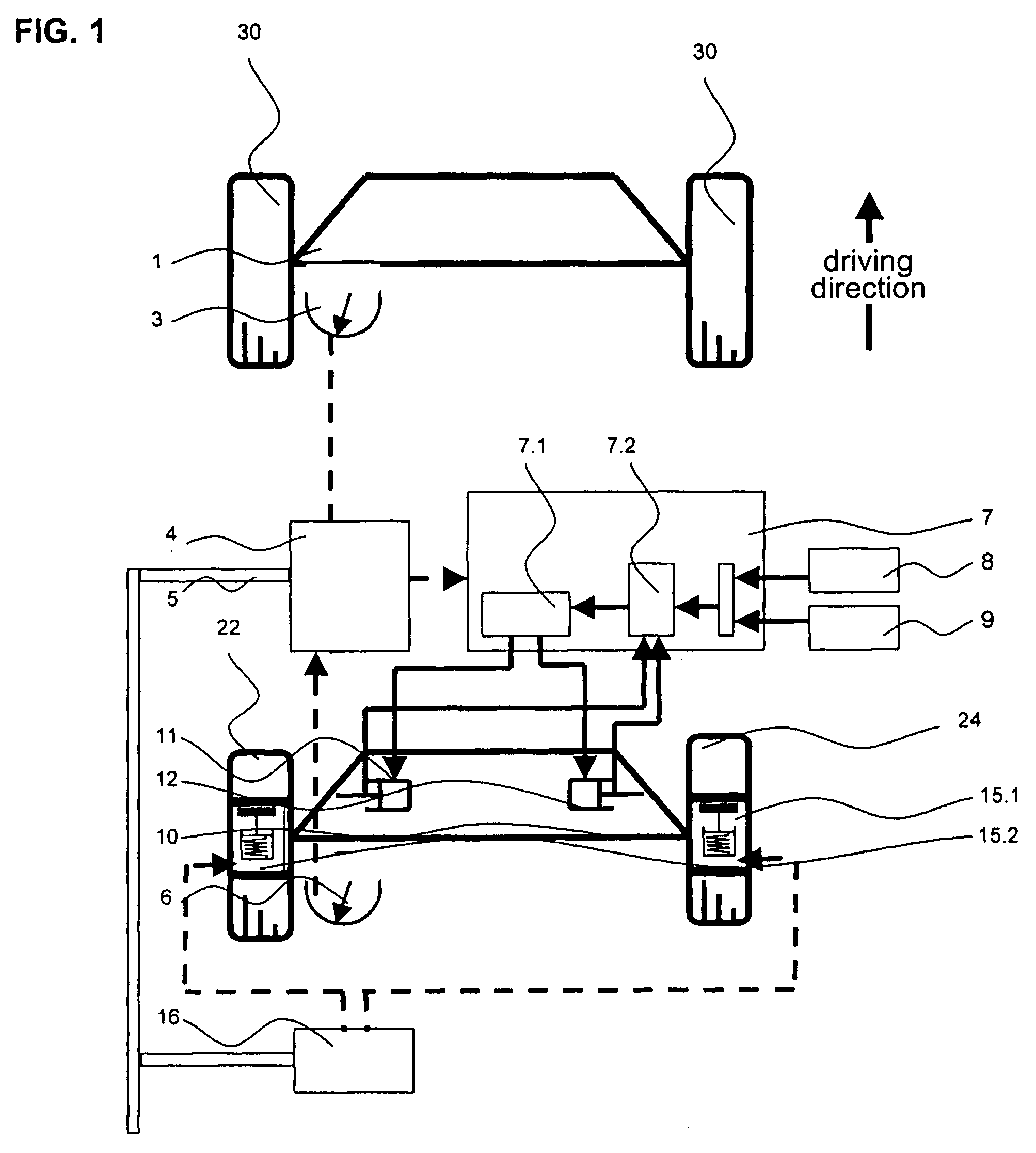
[0049]In contrast to that, in the present invention as it is shown in FIG. 1, a braking system 15 with electro-pneumatic actuators 15.1, 15.2 for selectively braking the wheels 22, 24 in order to achieve a desired steering position in the event of an error. Along with the control computer 4, the embodiment shown in FIG. 1 comprises a control computer 16 for the brake and the associated actuators 15.1, 15.2. In the event of severe steering system errors, the affected rear axle 10 is steered to a desired position by selectively braking the individual wheels 22, 24.
[0050]In the embodiment shown in FIG. 1, the safety function is automatically triggered by a steering computer which may be integrated in the control computer 4. In the event of particular errors, such as a failure of the steering computer 4 or of an actual angle sensor 6, steering or centering actions are no longer possible. In such cases, the rear axle 10 would be locked in its current position.
[0051]Another exemplary embo...
third embodiment
[0052]the present invention is shown in FIG. 3. Compared to the embodiments shown in FIGS. 1 and 2, this embodiment includes another, additional actual angle sensor 18. In the event of a faulty actual angle sensor 6, the additional actual angle sensor 18 ensures that the affected rear axle 10 remains positionable by braking the individual wheels 22, 24. Vehicles with several actively steered rear axles 10 may comprise two actual angle sensors 6, 18 for each actively steered rear axle 10 to provide redundancy.
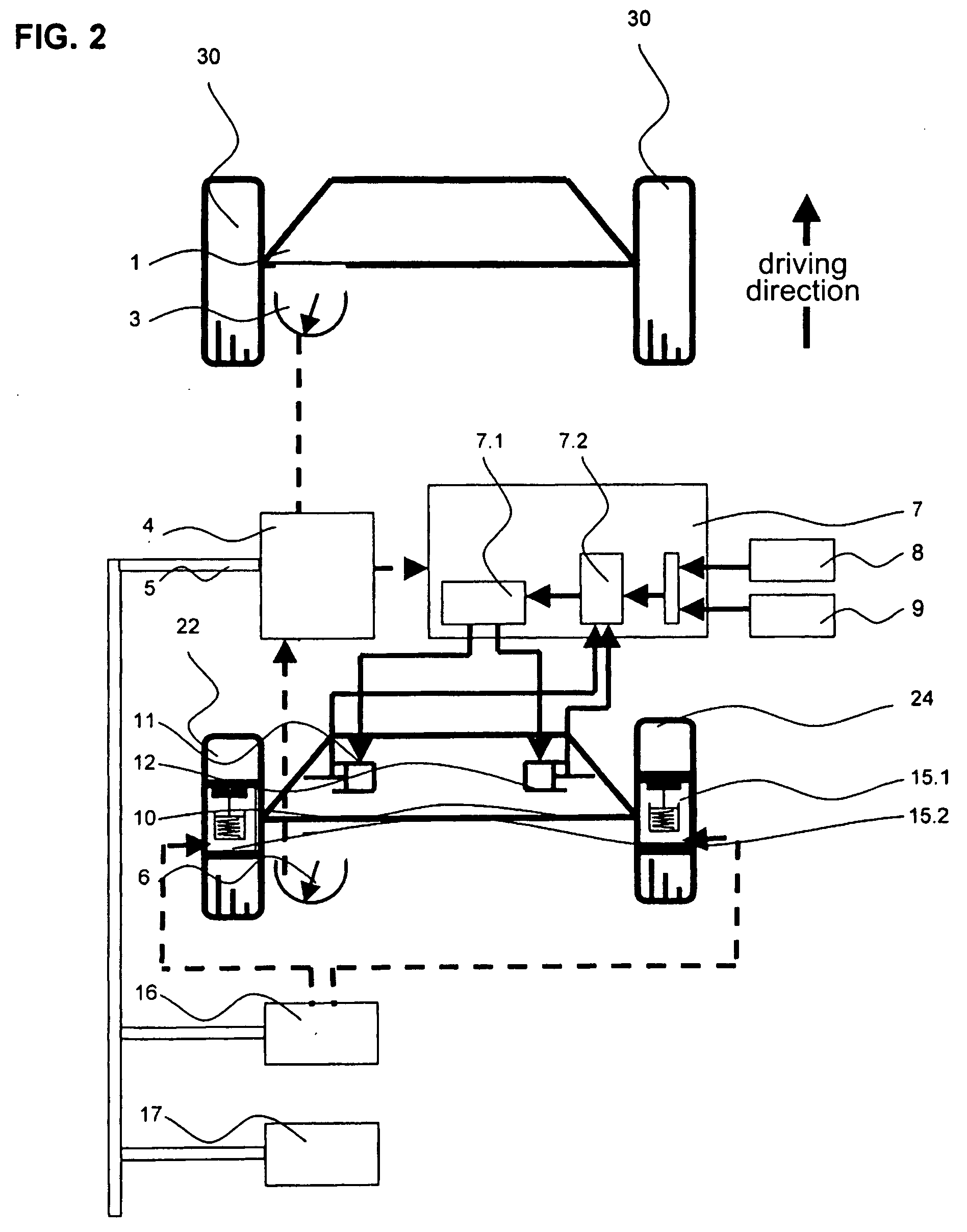
[0053]Finally, FIG. 4 shows another embodiment of the present invention. Compared to the embodiments of the present invention shown in FIGS. 1 to 3, another setpoint angle sensor 19 is provided on the front axle 1. Even if the first setpoint angle sensor 3 fails, the affected rear axle 10 may still be positioned by braking individual wheels 22, 24; to this end, the second setpoint angle sensor 19 is connected to the additional control computer 17.
[0054]In the event of an error w...
PUM
 Abstract
Description
Claims
Application Information