External device, electronic flash device, and camera

a technology of electronic flash and external device, which is applied in multiplex communication, television systems, instruments, etc., can solve the problems of difficulty in enhancing the accuracy of synchronization of light emission timing of master electronic flash devices, and achieve the effect of enhancing the accuracy of synchronization

Active Publication Date: 2009-05-28
NIKON CORP
View PDF16 Cites 81 Cited by
  • Summary
  • Abstract
  • Description
  • Claims
  • Application Information

AI Technical Summary

Benefits of technology

[0007]However such a conventional system starts measurement by a timer from the time when the light emission of the master electronic flash device is detected and accordingly it has been difficult to enhance the a...

Problems solved by technology

However such a conventional system starts measurement by a timer from the time when the light emission of the master electronic flash device is detected and accordingly it has been difficult to enhance the accu...

Method used


Image

  • External device, electronic flash device, and camera
  • External device, electronic flash device, and camera
  • External device, electronic flash device, and camera

Examples


Embodiment Construction

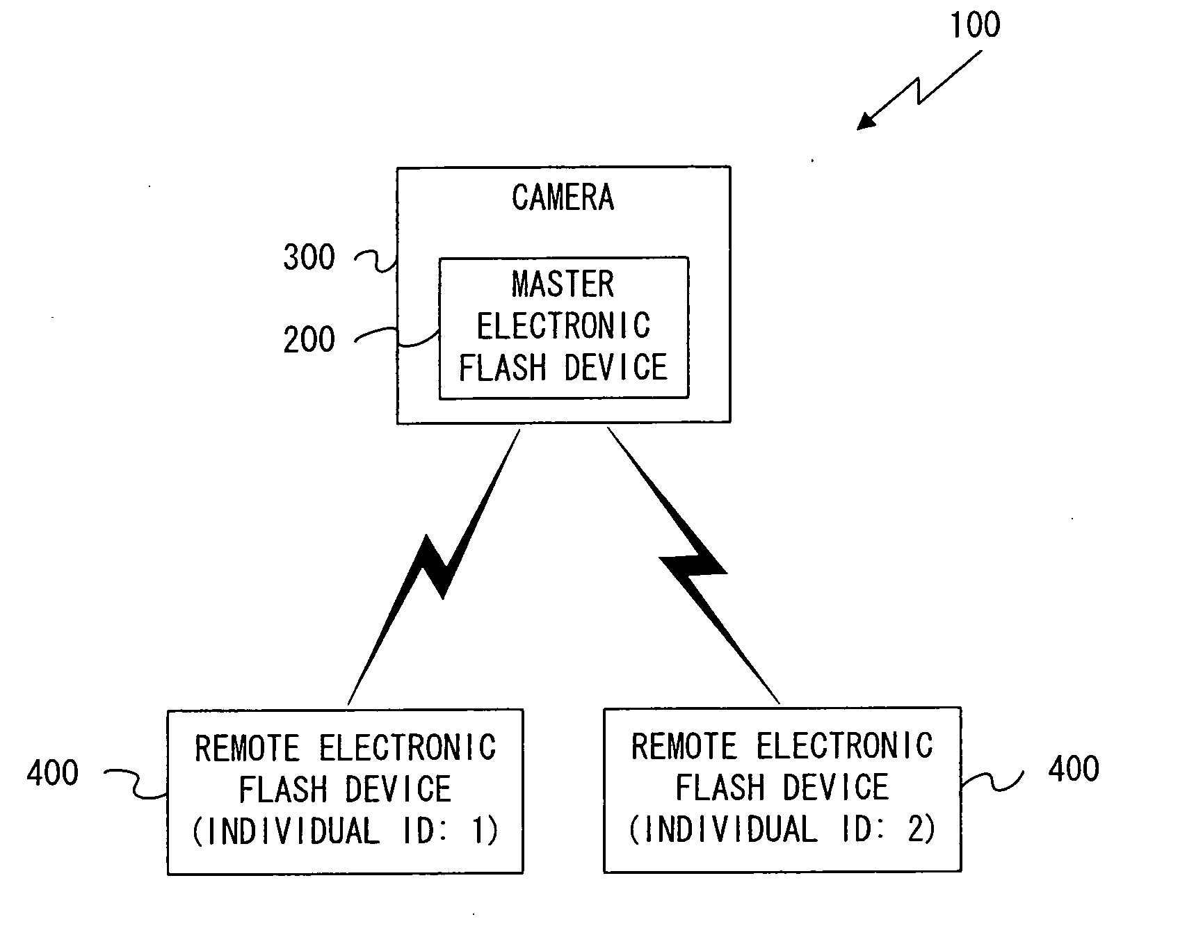
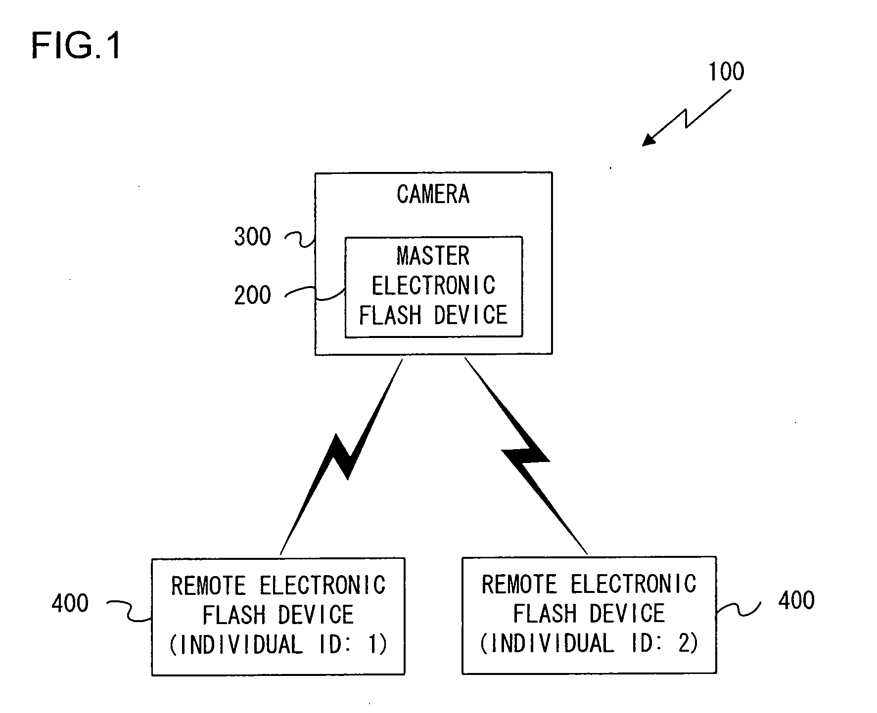
[0060]FIG. 1 is a block diagram showing the structure of the light emission control system according to an embodiment of the present invention. In this light emission control system 100, a camera 300 to which an electronic flash device (a master electronic flash device) 200 is fitted and one or more external electronic flash devices (remote electronic flash devices) 400 are connected together via wireless communication using ICs for wireless communication via wireless LAN, Bluetooth, ZigBee or the like. It should be understood that this light emission control system 100 consists of a single camera 300 to which a master electronic flash device 200 is fitted and at least one remote flash device 400 that constitutes an external device. In FIG. 1, however, a concrete example is shown of a case that consists of a single camera 300 and two remote flash devices 400.

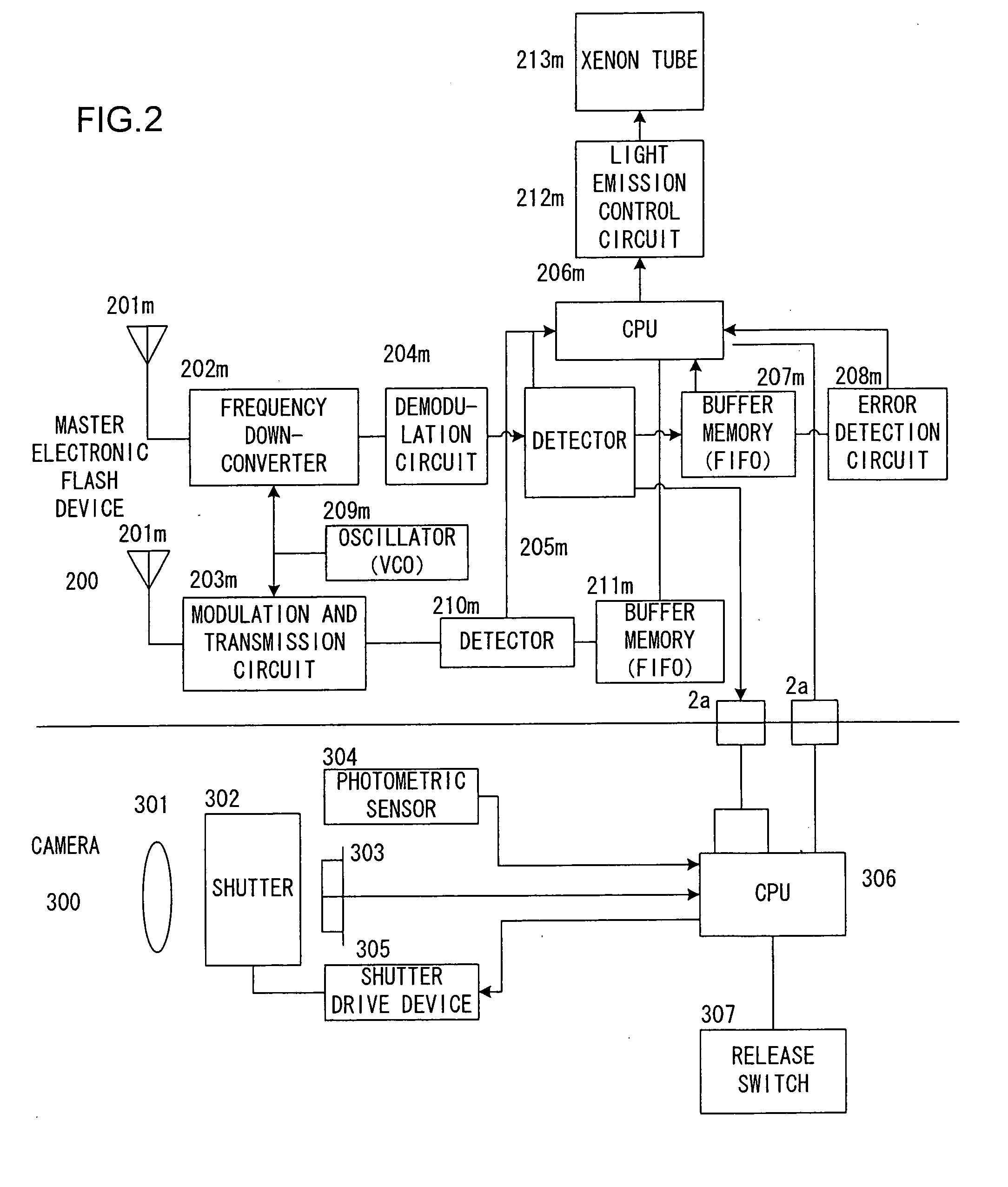
[0061]A block diagram of this camera 300 with the master electronic flash device 200 fitted thereto is shown in FIG. 2. The ma...


PUM


Abstract

The external device, for example, an electronic flash device, is wirelessly connectable to an information communication device, for example, a camera. The external device includes: a synchronization data creation unit that outputs synchronization data for synchronization of timing of processing related to photography; a packet creation unit that creates a communication packet including control information; and a packet output unit that outputs the communication packet to the exterior by wireless communication. The packet creation unit includes a packet reception unit that receives the communication packet; a detection unit that detects the synchronization data before all of the received communication packets received by the packet reception unit has been read in; and a signal output unit that outputs a synchronization signal used for establishing synchronization of the timing of the processing related to photography on the basis of detection by the detection unit of the synchronization data.

Description

INCORPORATION BY REFERENCE[0001]The disclosures of the following priority application and international application are herein incorporated by reference: Japanese Patent Application No. 2006-204753 filed Jul. 27, 2006; and International Application No. PCT / JP2007 / 064788 filed Jul. 27, 2007.CROSS-REFERENCE TO RELATED APPLICATION(S)[0002]This application is a continuation of International Application No. PCT / JP2007 / 064788 Jul. 27, 2007.BACKGROUND OF THE INVENTION[0003]1. Field of the Invention[0004]The present invention relates to an external device to be connected to a camera upon use, to an electronic flash device, and to a camera.[0005]2. Description of Related Art[0006]The following type of wireless light increasing system is known. With this system, an auxiliary electronic flash device starts its own light emission operation upon detection of the light emission of a master electronic flash device that is connected to a camera. (Refer to Japanese Laid-Open Patent Publication H06-2...

Claims


Application Information

Patent Timeline
IPC IPC(8): H04N5/232
CPCG03B15/02G03B15/05H04N5/2354H04N5/2256H04J3/0638G03B2215/0557H04N23/56H04N23/74
Inventor OGASAWARA, AKIRA
Owner NIKON CORP
Why Eureka
Try Eureka