Zoom lens and image capturing apparatus

Inactive Publication Date: 2009-05-28
SONY CORP
View PDF3 Cites 7 Cited by
  • Summary
  • Abstract
  • Description
  • Claims
  • Application Information

AI Technical Summary

Benefits of technology

[0015]Accordingly, the present invention provides a zoom lens including a lens group disposed in the vicinity of an aperture stop and having two subgroups. By shifting one of the two subgroups so as to shift an image, the size of the lens group including a shi

Problems solved by technology

Consequently, it is difficult to reduce the weight and the size of the zoom lens.
However, to sufficiently increase the distance between the two subgroups, the size of the zoom lens cannot be reduced.
Thus, the distance between the t

Method used


Image

  • Zoom lens and image capturing apparatus
  • Zoom lens and image capturing apparatus
  • Zoom lens and image capturing apparatus

Examples


first embodiment

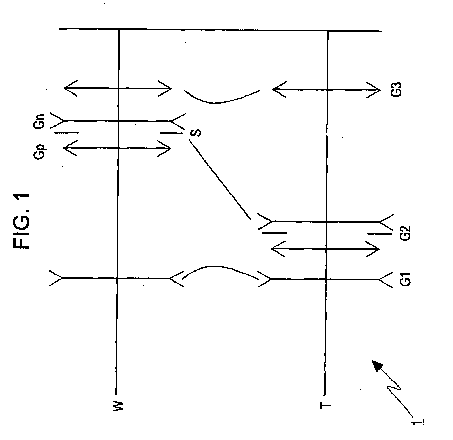
[0074]FIG. 1 is a schematic illustration of a refractive power arrangement diagram of a zoom lens 1 including three lens groups according to the present invention.

[0075]The zoom lens 1 includes three lens groups: a first lens group G1 having a negative refractive power, a second lens group G2 having a positive refractive power, and a third lens group G3 having a positive refractive power disposed in this order from the object side. The second lens group G2 that serves as a shift lens group includes a positive subgroup Gp having a positive refractive power, an aperture stop S, and a negative subgroup Gn having a negative refractive power disposed in this order from the object side. When the focal length changes from the wide-angle setting in which the focal length is the shortest (a setting indicated by a reference symbol W in the upper section of FIG. 1) to the telephoto setting in which the focal length is the longest (a setting indicated by a reference symbol T in the lower sectio...

second embodiment

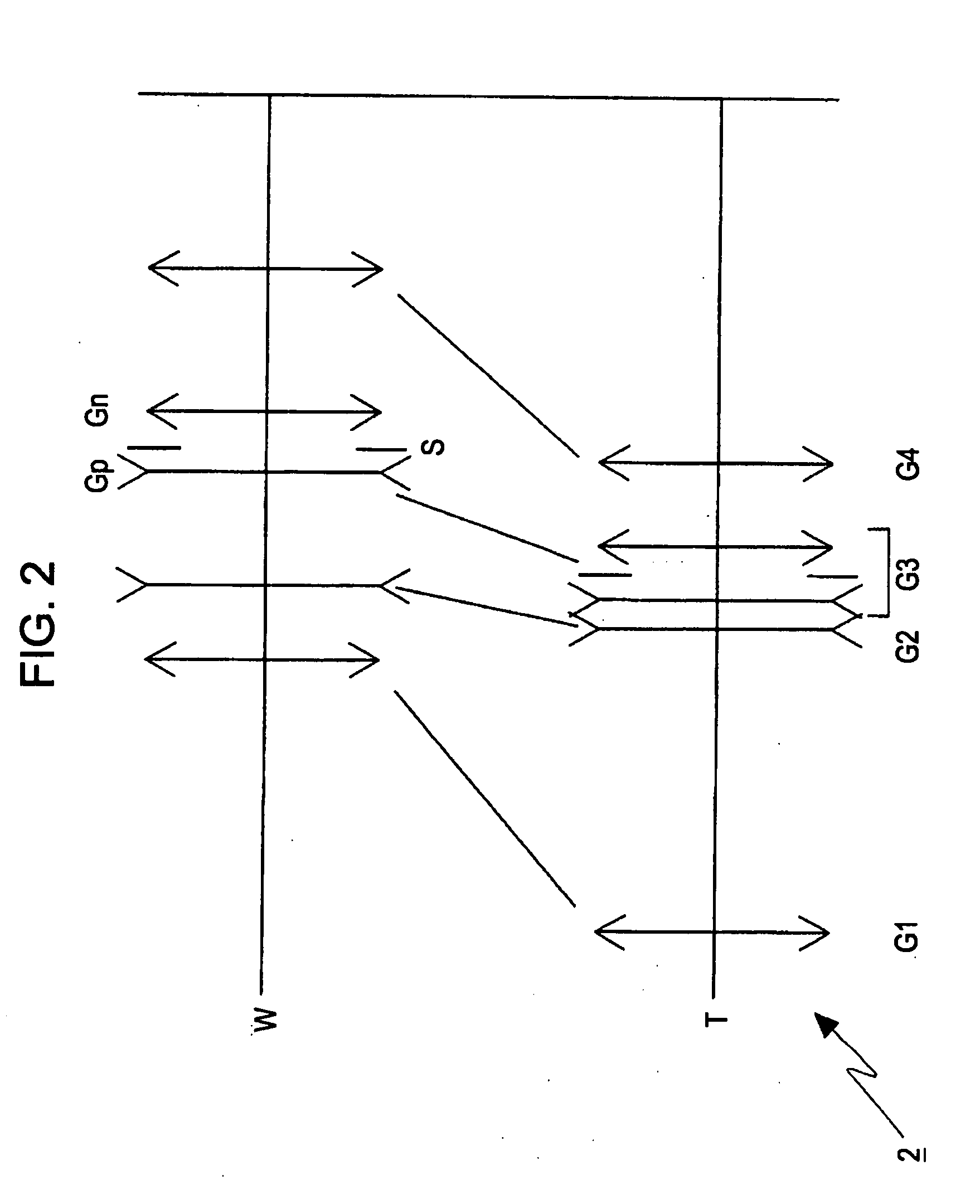
[0077]FIG. 2 is a schematic illustration of a refractive power arrangement diagram of a zoom lens 2 including four lens groups according to the present invention.

[0078]The zoom lens 2 includes four lens groups: a first lens group G1 having a positive refractive power, a second lens group G2 having a negative refractive power, a third lens group G3 having a positive refractive power, and a fourth lens group G4 having a positive refractive power disposed in this order from the object side. The third lens group G3 that serves as a shift lens group includes a negative subgroup Gn having a negative refractive power, an aperture stop S, and a positive subgroup Gp having a positive refractive power disposed in this order from the object side.

[0079]When the focal length changes from the wide-angle setting in which the focal length is the shortest (a setting indicated by a reference symbol W in the upper section of FIG. 2) to the telephoto setting in which the focal length is the longest (a ...

third embodiment

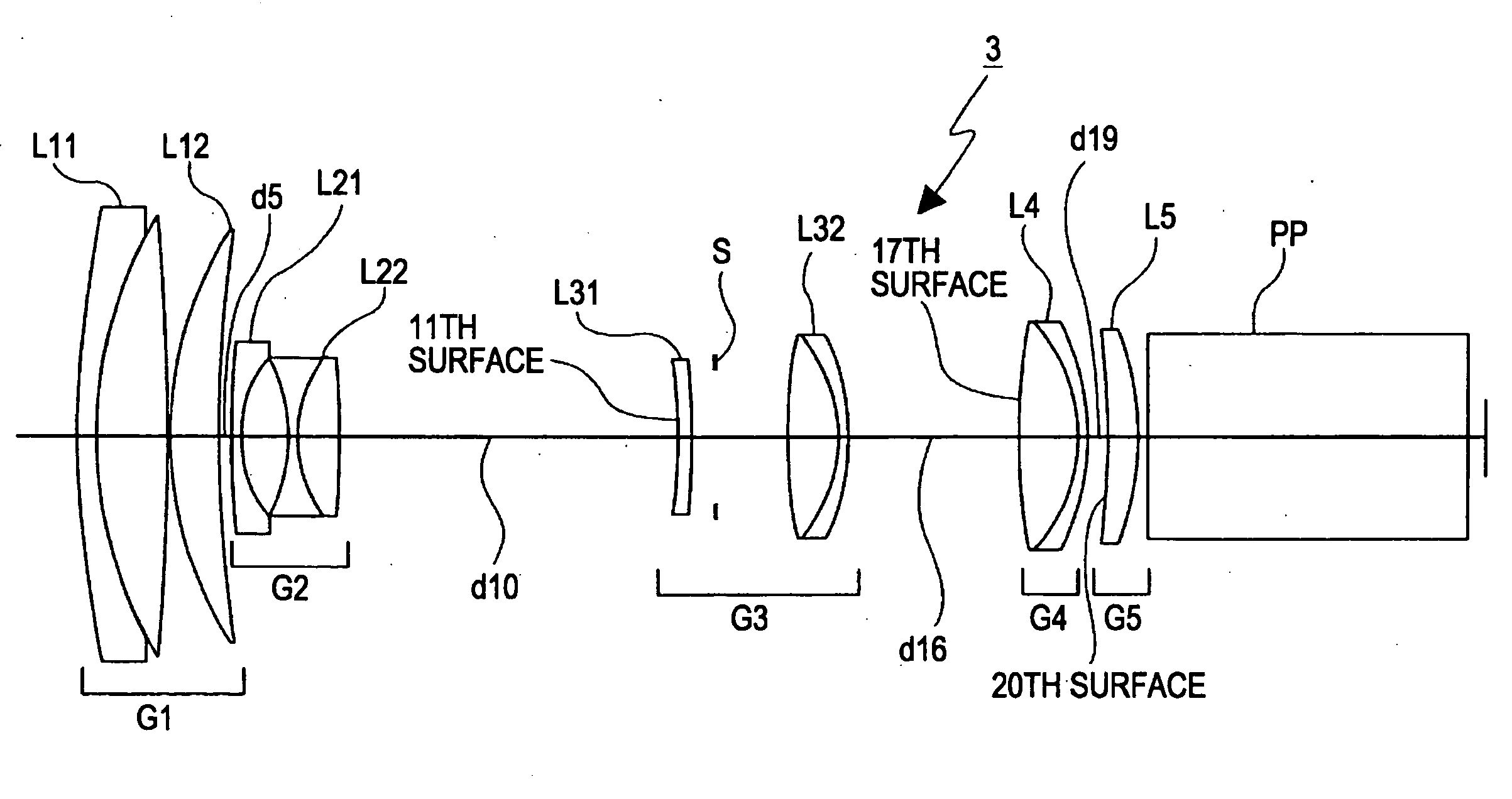
[0080]FIG. 3 is a schematic illustration of a refractive power arrangement diagram of a zoom lens 3 including five lens groups according to the present invention.

[0081]The zoom lens 3 includes five lens groups: a first lens group G1 having a positive refractive power, a second lens group G2 having a negative refractive power, a third lens group G3 having a positive refractive power, a fourth lens group G4 having a positive refractive power, and a fifth lens group G5 having a positive refractive power arranged in this order from the object side. When the lens position setting changes from the wide-angle setting (a setting indicated by a reference symbol W in the upper section of FIG. 3) to the telephoto setting (a setting indicated by a reference symbol T in the lower section of FIG. 3), the first lens group G1 remains stationary along the optical axis, the second lens group G2 is moved towards the image side, and the third lens group G3 remains stationary along the optical axis. In ...


PUM


Abstract

The object of the present invention is to provide a zoom lens in which a lens group located in the vicinity of an aperture stop includes two subgroups and one of the subgroups is shifted so that an image is shifted. Thus, an increase in the size of lens groups including a shift lens group can be prevented. In addition, the sensitivity with respect to the axis tilt can be reduced while maintaining a sufficient distance between the two subgroups without increasing the size of the lens groups. Accordingly, a sufficient performance can be provided.
A zoom lens 3 includes at least three lens groups, that is, a negative lens group G2 having a negative refractive power, a shift lens group G3, and a positive lens group G4 having a positive refractive power arranged in this order from an object side. When the lens position is moved from a wide-angle setting to a telephoto setting, at least the negative lens group and the positive lens group move so that a distance between the negative lens group and the shift lens group is decreased and a distance between the shift lens group and the positive lens group is changed. The shift lens group includes at least two subgroups L31 and L32, an aperture stop S is disposed between the two subgroups, and an image is capable of being shifted by shifting one of the subgroups L32 in a direction substantially perpendicular to an optical axis. The following conditional expression (1) is satisfied:
Ds/ft>0.1  (1)
where Ds denotes a distance along the optical axis extending from the lens surface that is the closest to the image among the lens surfaces of the subgroup located on the object side to the lens surface that is the closest to the object among the lens surfaces of the subgroup located on the image side, and ft denotes the focal length of the entire lens system in the telephoto setting.

Description

TECHNICAL FIELD[0001]The present invention relates to a novel zoom lens and an image capturing apparatus. More particularly, the present invention relates to a zoom lens suitable for cameras, such as video cameras and digital still cameras, that receive light using an image sensing device and suitable for correcting blurring of an image due to shaking of the cameras and an image capturing apparatus including the zoom lens.BACKGROUND ART[0002]A method has been known in which a subject image is formed on an image sensing device using a photoelectric transducer, such as a charged coupled device (CCD) or a complementary metal-oxide semiconductor (CMOS) that serves as recording means of a camera, and the light intensity of the subject image is converted to an electrical output by the photoelectric transducer and is recorded.[0003]In recent years, with the advancement of microfabrication techniques, central processing units (CPUs) have been increasing in processing speed and recording med...

Claims


Application Information

Patent Timeline
IPC IPC(8): G02B27/64G02B15/16
CPCG02B27/646G02B15/173G02B15/144113G02B15/145129G02B15/143507G02B13/009G02B3/0087G03B17/12G02B2003/0093H04N23/55
Inventor OHTAKE, MOTOYUKI
Owner SONY CORP
Why Eureka
Try Eureka