
Vehicle navigation apparatus and vehicle navigation program

a vehicle navigation and vehicle navigation technology, applied in the field of vehicle navigation technique, can solve the problem that the content of the precedingly conducted branch guidance may be forgotten

Inactive Publication Date: 2009-05-28
AISIN AW CO LTD
View PDF16 Cites 29 Cited by
  • Summary
  • Abstract
  • Description
  • Claims
  • Application Information

AI Technical Summary

Benefits of technology

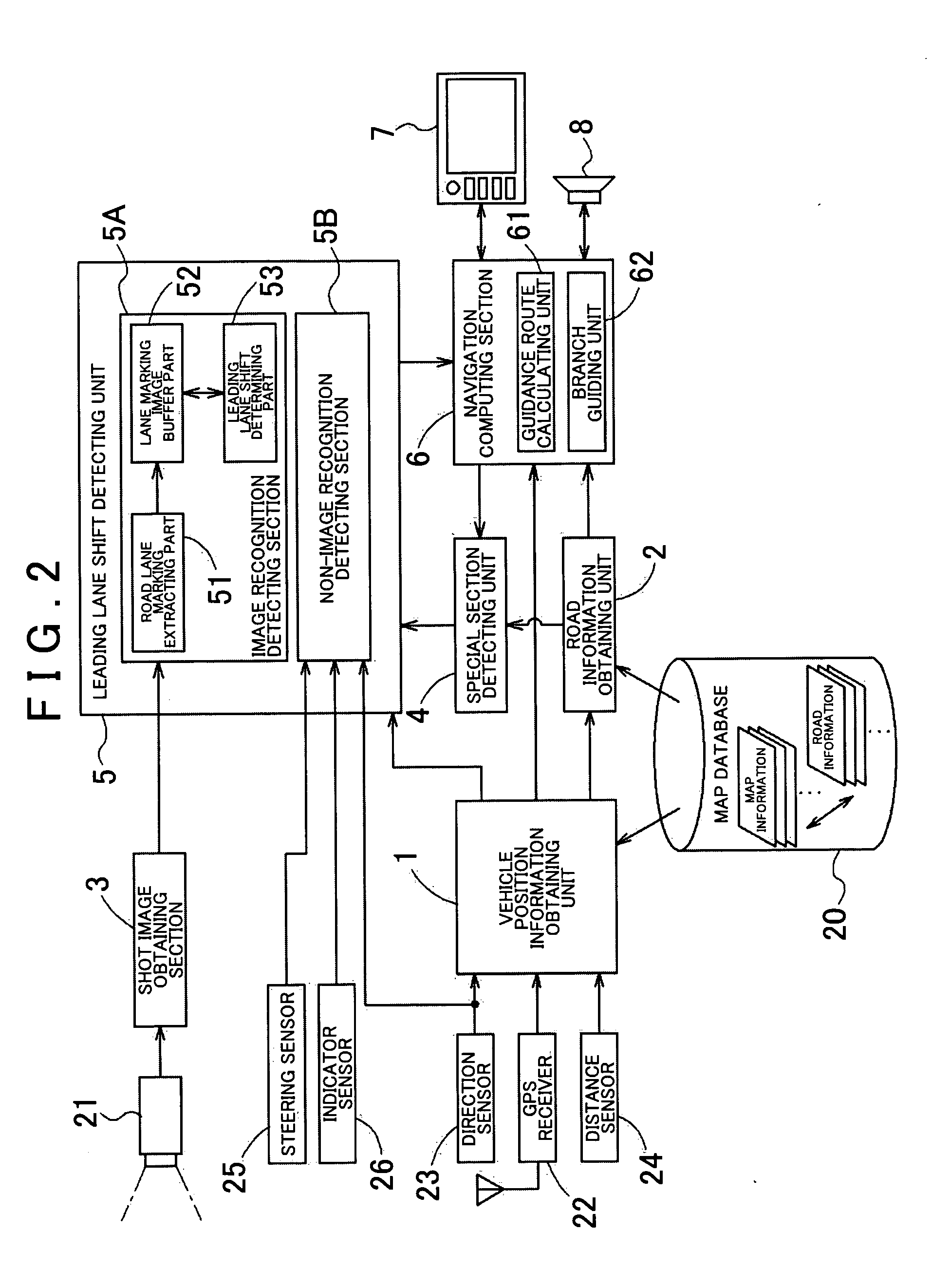
[0013]The leading lane shift detecting unit detecting the shift of the vehicle from the main line into the leading lane of the special section can be realized by some different methods. Among them, one to be proposed as a preferable leading lane shift detecting unit in a case where a camera capable of including at least road lane markings in the vicinity of the vehicle in a shooting range is mounted on the vehicle is composed of an image recognition detecting section detecting the shift of the vehicle into the leading lane based on the constant detection of the road lane markings by the image recognition of the shot image from the camera. Here, “road lane markings” refer to solid or dashed white lines, yellow lines, and the like marked as border lines of the traffic lane on both sides or one side of the lane (traffic lane), and generally, the road lane markings of dashed lines are marked in the boundary between a traveling lane and the leading lane. Therefore, when the road lane markings at a left side of the traveling lane change from solid lines to dashed lines and the dashed lines go from left to right, for example, it is possible to detect from the image recognition that the vehicle shifts from the traveling lane into the leading lane at the left side. A presence of the leading lane and a positional relationship between the leading lane and the traveling lane can be known from map information and road information stored in the navigation apparatus, so that by using the image recognition technique as described above, it is possible to relatively easily detect the shift of the vehicle into the leading lane.
[0014]It is allowable that, without performing the leading lane shift detection by capturing the temporal change in the aforementioned lane marking images through the image recognition, a leading lane shift determination is performed through a pattern matching processing in which the leading lane shift detecting unit is formed of an image recognition detecting section detecting the shift of the vehicle into the leading lane based on types of the road lane markings obtained through the image recognition of the shot image from the camera, and a lane marking image when the vehicle is traveling on the leading lane is set as a standard pattern, for instance. In this case, compared to the technique for image-recognizing the temporal change, it is possible to save on a considerable amount of memory capacity temporarily storing a lot of shot images being received constantly.
[0015]The leading lane shift detection through the image recognition using the shot image from the camera may become impossible to be conducted depending on an environment such as snow. By considering such a case, or by considering a case where the leading lane shift detection is applied to a vehicle having no camera capable of including the road lane markings in the shooting range, it is also one of the preferred embodiments that the leading lane shift detecting unit includes a non-image recognition detecting section detecting the shift of the vehicle into the leading lane based on at least one signal among a direction detection signal, a steering operation signal and an indicator operation signal. The direction detection signal is generated from an output signal of a gyro, a geomagnetic sensor or the like, the steering operation signal is generated from an output signal of a sensor detecting a steering angle, and the indicator operation signal can be obtained from an indicator (direction indicator) control system. These signals are basically prepared in a general vehicle such as a passenger vehicle, so that they can be used without any special cost, which is advantageous. It is possible to estimate the shift of the vehicle into the leading lane by determining the presence of the leading lane and the positional relationship between the leading lane and the traveling lane from the map information and the road information, and based on, preferably, a plurality of combinations of the aforementioned signals. Further, by combining the aforementioned image recognition detecting section and the non-image recognition detecting section, a further reliable leading lane shift detecting unit can be configured.

Problems solved by technology

JP-A2006-23159, in a travel route where a vehicle first shifts into a leading lane and enters an actual branch path after traveling on the leading lane and then diverges at a next branch point, if shift guidance for the leading lane as well as the branch guidance for the branch point on the branch path diverges from the main line are conducted, there is generated a problem that the contents of the precedingly conducted branch guidance may be forgotten when the vehicle shifts into the leading lane and travels thereon.

Method used


Image

  • Vehicle navigation apparatus and vehicle navigation program
  • Vehicle navigation apparatus and vehicle navigation program
  • Vehicle navigation apparatus and vehicle navigation program

Examples


Embodiment Construction

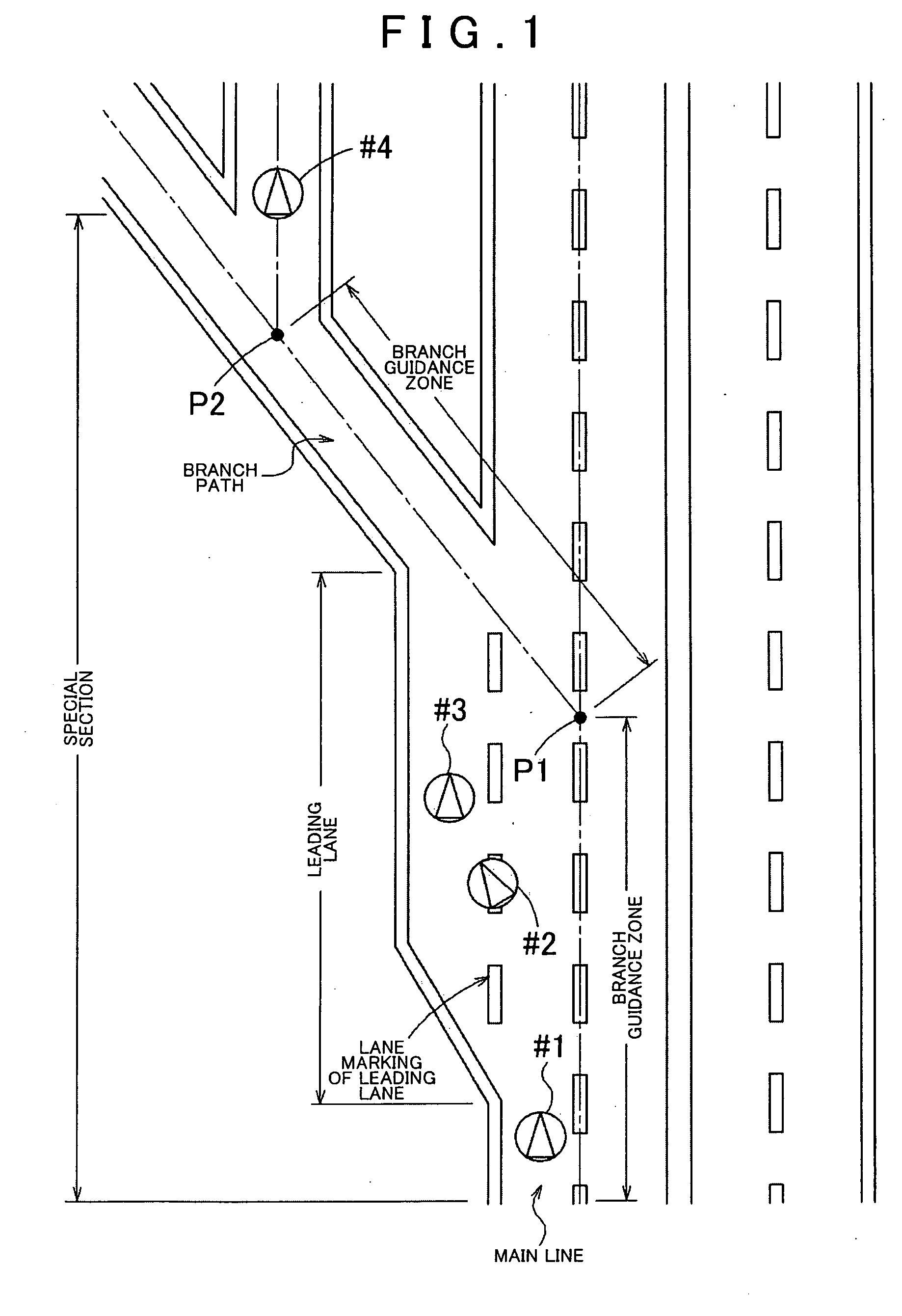
[0025]Before explaining a concrete configuration of a vehicle navigation apparatus according to the present invention, a basic principle thereof will be explained using a schematic view of FIG. 1.

[0026]FIG. 1 shows a special section to be a target of a navigation processing according to the present invention having a branch point P1 with leading lane through which a branch path diverges from a main line in an express way, a highway and the like. Note that, in order to simply explain the present invention, it is supposed that on the branch path which diverges from the branch point P1 with leading lane in the special section, a branch point P2 exists within a predetermined close distance from the branch point P1 with leading lane (hereinafter, such a branch point is referred to as a close-distance branch point). Specifically, in an explanation of the basic principle of the invention, travel guidance when a section as shown in FIG. 1 in which a vehicle enters the branch path from the m...


PUM


Abstract

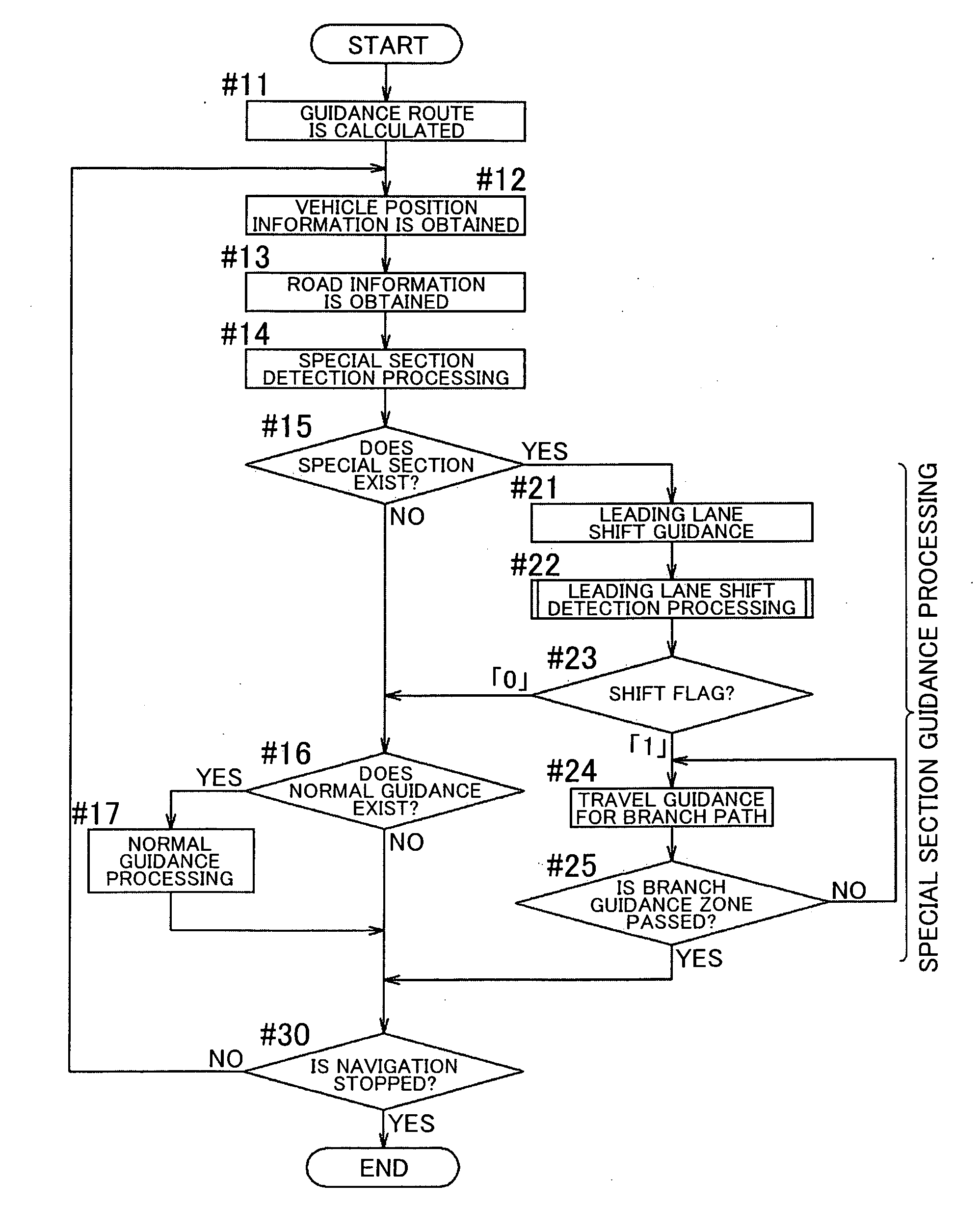
A vehicle navigation apparatus includes: a vehicle position information obtaining unit detecting a vehicle position; a special section detecting unit detecting a special section from a guidance route ahead of the vehicle position; a leading lane shift detecting unit detecting a shift of the vehicle from a main line to the leading lane in the special section; and a branch guiding unit conducting branch guidance for a branch point with a leading lane and conducting, in response to the detection of the shift of the vehicle into the leading lane detected by the leading lane shift detecting unit, travel guidance for a branch path.

Description

[0001]The disclosure of Japanese Patent Application No. 2007-281872 filed on Oct. 30, 2007 including the specification, drawings and abstract is incorporated herein by reference in its entirety. BACKGROUND OF THE INVENTION[0002]1. Field of the Invention[0003]The present invention relates to a vehicle navigation technique for performing travel guidance for a branch path to be a guidance target existing on a guidance route leading to a destination.[0004]2. Description of the Related Art[0005]There is known a navigation apparatus which detects a position of a vehicle using a GPS and the like, displays both a symbol indicating the position and a road map on a display, and informs travel guidance by displaying it on the display or by a voice in a timely manner so as to facilitate a smooth traveling along a set guidance route to a destination. For example, when a branch point for which the travel guidance should be performed approaches on the guidance route, guidance such as “Turn right a...

Claims


Application Information

Patent Timeline
IPC IPC(8): G01C21/36
CPCG01C21/3658G01C21/3655
Inventor KATOU, KIYOHIDE
Owner AISIN AW CO LTD
Learn More