Expander-compressor unit

a compressor unit and compressor technology, applied in the direction of machines/engines, liquid fuel engines, lighting and heating apparatus, etc., can solve the problems of reducing the indoor heating capacity during heating, the indoor cooling capacity during cooling is not without problems, and the expansion mechanism to the expansion mechanism via oil is suppressed, so as to suppress the heat transfer

Inactive Publication Date: 2009-06-04
PANASONIC CORP
View PDF35 Cites 29 Cited by
  • Summary
  • Abstract
  • Description
  • Claims
  • Application Information

AI Technical Summary

Benefits of technology

[0025]In the latter one of the expander-compressor units, the oil pump is disposed between the compression mechanism and the expansion mechanism. Therefore, in a state in which the closed casing is placed upright, the oil supply passage extending toward the mechanism that is located in the upper space may be formed without passing through the mechanism that is located in the lower space. Accordingly, the oil pumped up by the oil pump may be supplied to the mechanism that is located in the upper space without passing through the mechanism that is located in the lower space. As a result, heat transfer from the compression mechanism to the expansion mechanism via the oil is suppressed. Moreover, the partition wall restricts travelling of the oil between the upper space and the lower space, and this also serves to suppress the heat transfer. However, the communication passage is formed in the partition wall, and transfer of the oil is permitted between the upper space and the lower space through this communication passage. Therefore, it is unnecessary to take a measure to balance the amount of the oil present in the upper space and the amount of the oil present in the lower space.

Problems solved by technology

However, the expander-compressor unit is not without a problem that is associated with oil.
In the case of air conditioners, this means a decrease of indoor heating capacity during heating or a decrease of indoor cooling capacity during cooling.

Method used


Image

  • Expander-compressor unit
  • Expander-compressor unit
  • Expander-compressor unit

Examples


first embodiment

[0044]Hereinbelow, one embodiment of the present invention is described with reference to the appended drawings.

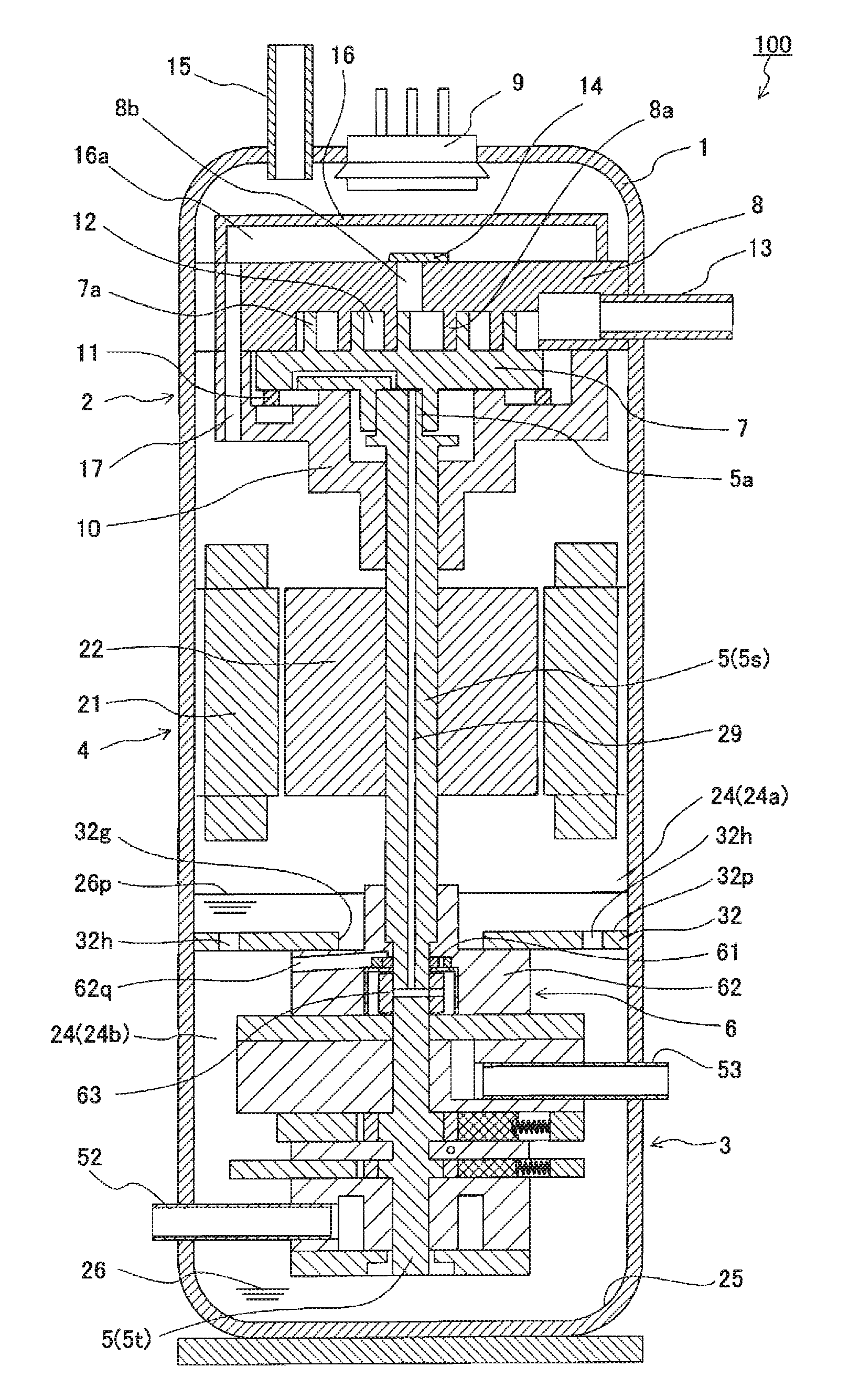
[0045]FIG. 1 is a vertical cross-sectional view illustrating an expander-compressor unit according to a first embodiment of the present invention. An expander-compressor unit 100 includes: a closed casing 1 having an internal space 24; a scroll-type compression mechanism 2 disposed above the internal space 24; a two-stage rotary type expansion mechanism 3 disposed below the internal space 24; a motor 4 disposed between the compression mechanism 2 and the expansion mechanism 3; an oil pump 6 disposed between the motor 4 and the expansion mechanism 3; a partition wall 32 disposed between the oil pump 6 and the motor 4; and a shaft 5 for coupling the compression mechanism 2, the expansion mechanism 3, and the motor 4 to each other. The motor 4 rotationally drives the shaft 5, whereby the compression mechanism 2 is operated. The expansion mechanism 3 converts the expansion for...

second embodiment

[0080]A vertical cross-sectional view of an expander-compressor unit according to a second embodiment is shown in FIG. 9, and a half section perspective view thereof is shown in FIG. 10. The expander-compressor unit 102 according to the present embodiment differs from the expander-compressor unit 100 according to the first embodiment in that it further has a reserve tank 67. The rest of the parts are common to the two embodiments.

[0081]The reserve tank 67 has an annular shape surrounding the oil pump 6 circumferentially. The reserve tank 67 is disposed adjacent to the partition wall 32 in the lower space 24b. The reserve tank 67 receives and stores the oil 26 that has travelled from the upper space 24a to the lower space 24b through the second through holes 32h of the partition wall 32. A gap 67h is formed between the reserve tank 67 and the oil pump 6 such that the oil 26 stored in the reserve tank 67 flows into the gap. Since the oil suction passage 62q opens in the gap 67h, the o...

third embodiment

[0086]An expander-compressor unit 104 shown in FIG. 12 differs from the expander-compressor unit 102 (see FIG. 9) according to the second embodiment in that it further has a buffer member 68. The rest of the parts are common to the two embodiments.

[0087]As illustrated in FIG. 12, the buffer member 68 is disposed between the motor 4 and the partition wall 32. The buffer member reduces turbulence of the oil level 26p in association with the rotational driving of the motor 4 to suppress the flow of the oil 26. Therefore, the oil 26 that fills the lower space 24b is not easily stirred by the swirling flow caused by the motor 4, so the oil 26 tends to have a temperature gradient along the axis direction easily. As a result, a desirable condition for the refrigeration cycle is produced, in which the oil 26 drawn by the oil pump 6 is at a relatively high temperature while the oil 26 remaining in the surrounding space of the expansion mechanism 3 is at a relatively low temperature.

[0088]The...


PUM


Abstract

An the expander-compressor unit (100) includes a closed casing (1) in which an oil can be stored in its bottom part, a compression mechanism (2) disposed in an upper part of the closed casing (1), an expansion mechanism (3) disposed in a lower part of the closed casing (1), a shaft (5) for coupling the compression mechanism (2) and the an expansion mechanism (3) to each other, and an oil pump (6), disposed between the compression mechanism (2) and the expansion mechanism (3), for supplying the oil (26) filling a surrounding space of the expansion mechanism (3) to the compression mechanism (2).

Description

TECHNICAL FIELD[0001]The present invention relates to an expander-compressor unit including a compression mechanism for compressing fluid and an expansion mechanism for expanding the fluid, the expander-compressor unit having an integral construction wherein the compression mechanism and the expansion mechanism are coupled to each other by a shaft.BACKGROUND ART[0002]Recently, as natural resource issues and global warming issues have become ever more serious, much research and development efforts have been invested in reducing energy consumption of heat pump apparatus used for water heaters and air conditioners. For example, conventional heat pump apparatuses have a mechanism of expanding refrigerant using an expansion valve, but there is an attempt to recover the energy of expansion of the refrigerant by employing a positive displacement expander to utilize it as auxiliary power for the compressor. Theoretically, through the recovery and utilization of the expansion energy of the r...

Claims


Application Information

Patent Timeline
Patent Type & Authority Applications(United States)
IPC IPC(8): F25B43/00
CPCF01C1/3564F01C11/008F01C21/04F04C2240/60F04C18/0215F04C23/008F04C29/025F04C2/102
Inventor TAKAHASHI, YASUFUMIHASEGAWA, HIROSHIMATSUI, MASARUOKAICHI, ATSUOOGATA, TAKESHI
Owner PANASONIC CORP
Why Eureka
Try Eureka