
Food Processor Cutting Device Having a Position Adjustment Function

Inactive Publication Date: 2009-06-04
HUNDRED MACHINERY ENTERPRISE
View PDF5 Cites 18 Cited by
  • Summary
  • Abstract
  • Description
  • Claims
  • Application Information

AI Technical Summary

Benefits of technology

[0007]Another objective of the present invention is to provide a cutting device, wherein the threaded rod of each of the position adjustment units is rotated to push the elastic member which pushes the pressing member to press the respective pivot shaft of the cutting unit to adjust the position of the respective cutting blade of the cutting unit so as to tighten and locate the cutting unit, thereby preventing the cutting unit from being loosened or vibrated.
[0008]A further objective of the present invention is to provide a cutting device, wherein the position adjustment units press the pivot shafts of the cutting unit to prevent a clearance from being formed between the cutting blades of the cutting unit, thereby enhancing the working efficiency and lifetime of the cutting unit.
[0009]A further objective of the present invention is to provide a cutting device, wherein the cutting blades of the cutting unit are movable simultaneously by connection between the driven posts of the cutting unit and the limit slots of the rotation disk of the transmission unit so that the cutting blades of the cutting unit are operated exactly and smoothly.
[0010]A further objective of the present invention is to provide a cutting device, wherein a user only needs to detach the propeller shaft of the push unit for maintenance of the cutting device without having to reset and test the driving unit, thereby facilitating maintenance of the cutting device.

Problems solved by technology

However, the cutting blades of the cutting unit become loosened easily during a long-term utilization, thereby greatly decreasing the working efficiency of the cutting unit.

Method used


Image

  • Food Processor Cutting Device Having a Position Adjustment Function
  • Food Processor Cutting Device Having a Position Adjustment Function
  • Food Processor Cutting Device Having a Position Adjustment Function

Examples


Embodiment Construction

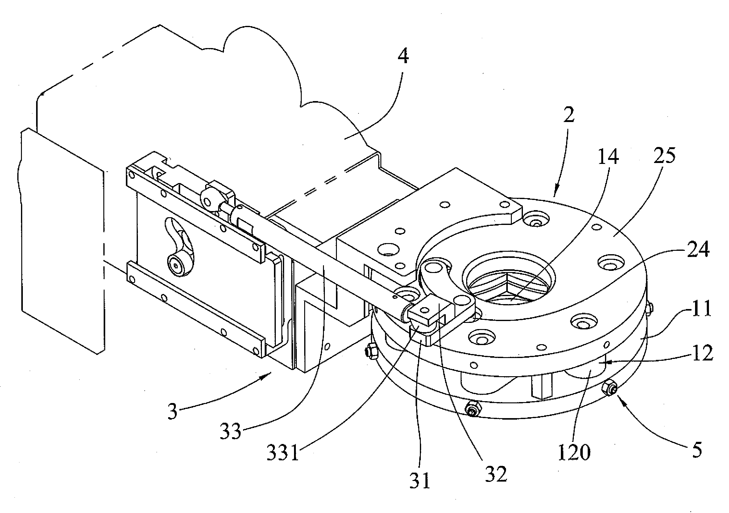
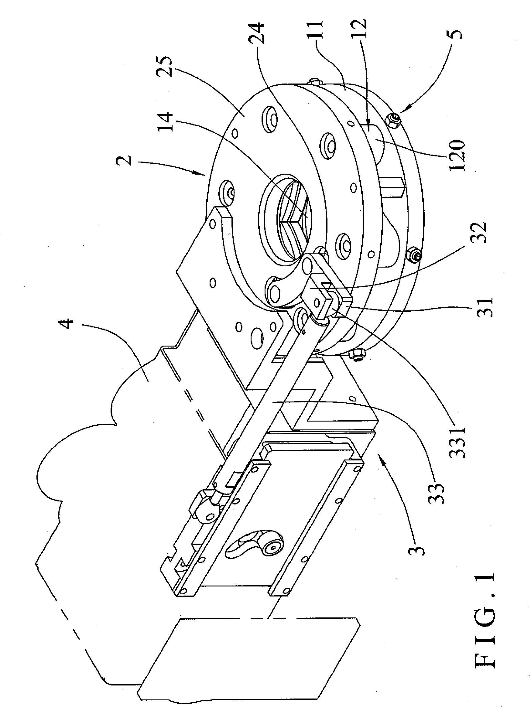
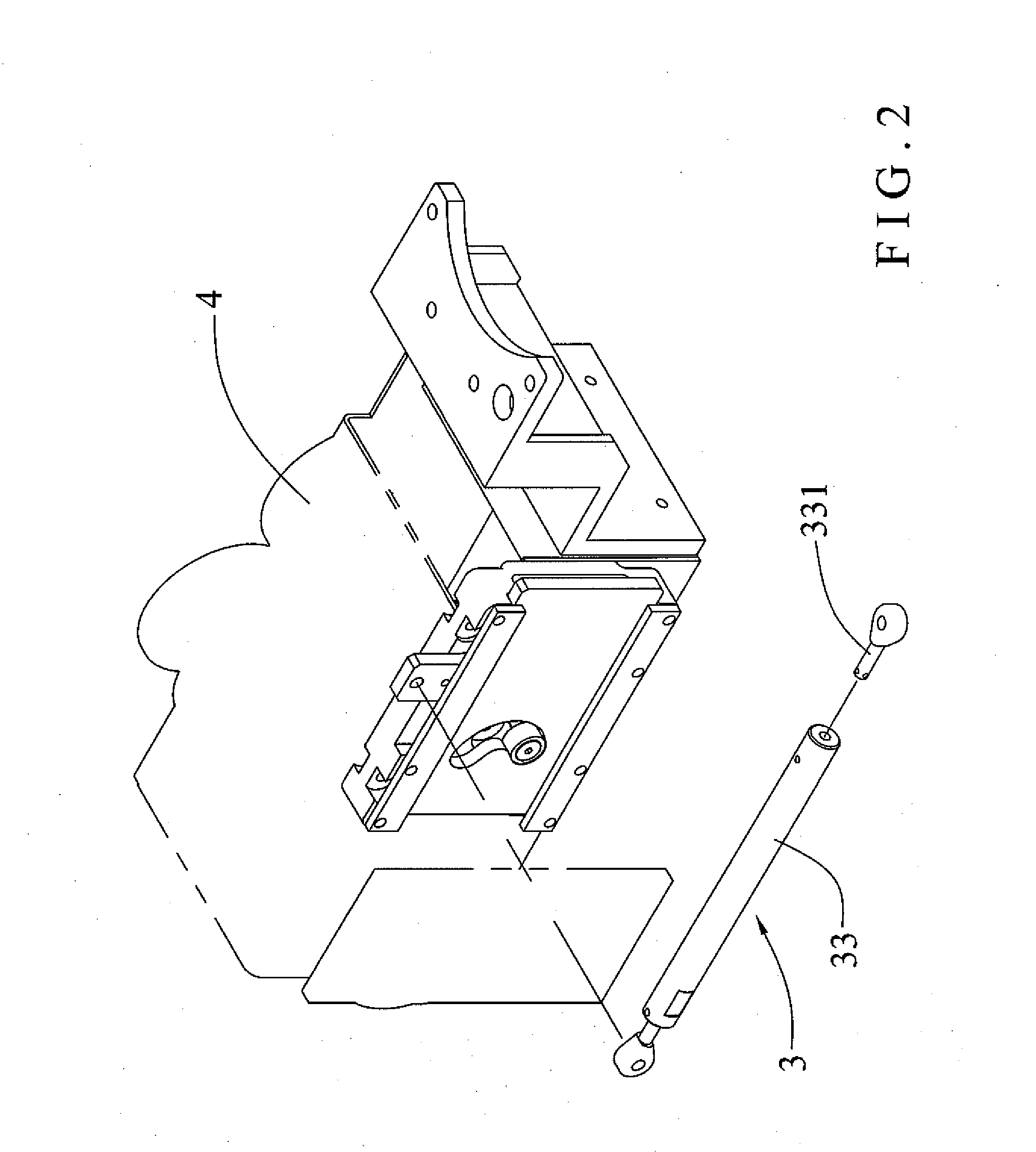
[0023]Referring to the drawings and initially to FIGS. 1-7, a cutting device for a food processor in accordance with the preferred embodiment of the present invention comprises a base 11, a cutting unit 12 mounted on the base 11, a plurality of position adjustment units 5 connected with the cutting unit 12 to adjust a position and tension of the cutting unit 12, a transmission unit 2 mounted on the base 11 and connected with the cutting unit 12 to drive the cutting unit 12, a push unit 3 connected with the transmission unit 2 to drive the transmission unit 2, and a driving unit 4 connected with the push unit 3 to drive the push unit 3.

[0024]The base 11 has a central portion provided with a through hole 14 to allow passage of dough (not shown). The base 11 has a surface provided with a plurality of pivot holes 15 surrounding the through hole 14 and a peripheral wall provided with a plurality of screw bores 16 each connected to a respective one of the pivot holes 15. The base 11 is pr...


PUM

PropertyMeasurementUnit
Shapeaaaaaaaaaa
Tensionaaaaaaaaaa

Abstract

A cutting device for a food processor includes a base, a cutting unit mounted on the base, a plurality of position adjustment units connected with the cutting unit to adjust a position of the cutting unit, a transmission unit mounted on the base and connected with the cutting unit to drive the cutting unit, a push unit connected with the transmission unit to drive the transmission unit, and a driving unit connected with the push unit to drive the push unit. Thus, each of the position adjustment units presses the cutting unit to adjust the position of the cutting unit so as to tighten and locate the cutting unit, thereby preventing the cutting unit from being loosened or vibrated.

Description

BACKGROUND OF THE INVENTION[0001]1. Field of the Invention[0002]The present invention relates to a cutting device and, more particularly, to a cutting device for a food processor.[0003]2. Description of the Related Art[0004]A conventional cutting device for a food processor comprises a base having a central portion provided with a through hole to allow passage of a dough, a cutting unit mounted on the base and including a plurality of cutting blades that are movable to cross the through hole of the base to cut the dough, and a driving unit connected with the cutting unit to drive the cutting blades of the cutting unit. However, the cutting blades of the cutting unit become loosened easily during a long-term utilization, thereby greatly decreasing the working efficiency of the cutting unit.BRIEF SUMMARY OF THE INVENTION[0005]In accordance with the present invention, there is provided a cutting device, comprising a base, a cutting unit mounted on the base, a plurality of position adju...

Claims


Application Information

Patent Timeline
IPC IPC(8): B26D1/01B26D1/45B26D7/00
CPCA21C11/103B26D2007/0037B26D1/30Y10T83/7788Y10T83/7797Y10T83/7818
Inventor TSAI, CHENG-YEN
Owner HUNDRED MACHINERY ENTERPRISE
Learn More