
Off-Axis Projection System and Method

a projection system and display system technology, applied in the field of distortion correction in an off-axis projection display system, can solve the problems of increasing the instantaneous fov of the projection lens, difficult to see the improvement, and occupying a relatively large space for cr

Active Publication Date: 2009-06-04
TEXAS INSTR INC
View PDF15 Cites 17 Cited by
  • Summary
  • Abstract
  • Description
  • Claims
  • Application Information

AI Technical Summary

Benefits of technology

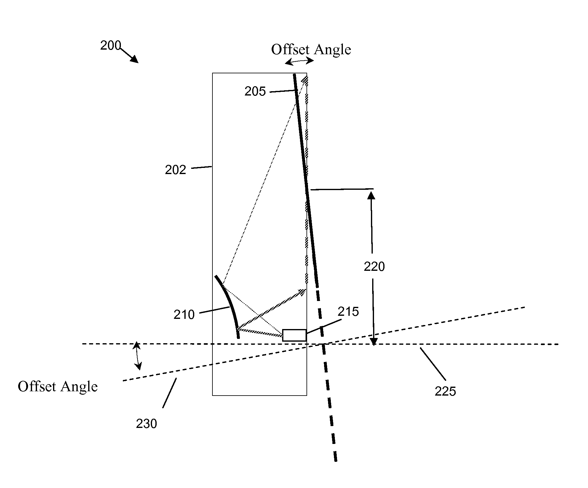
[0010]In accordance with an embodiment, an image projection system is provided. The image projection system includes a projection system and a display. The projection system has a first optical axis that is offset from an optical axis of the display by at least half the height of the display. The optical axes of the projection system and the display are non-parallel. Embodiments may be used to correct various types of distortion, including pincushion and barrel distortion. Embodiments may include one or more folding mirrors positioned to reflect light from the projection system to the display within a shorter distance. In some embodiments, the projection system and the display are rotated together such that a normal viewing angle may be maintained.
[0011]In accordance with another embodiment, a method of providing a rear projection system is provided. A projection lens system is provided such that the projection lens system projects an image along a first optical axis. A display plane is provided that is tilted such that the optical axis of the display plane is non-perpendicular to the first optical axis. Embodiments may include one or more folding mirrors for directing the image from the projection lens onto the display plane within a shorter distance. The display plane may be provided such that the tilt of the display plane causes a negative keystone effect or a positive keystone effect. The projection system and the display may also be provided such that a viewing angle normal to the display plane is maintained.

Problems solved by technology

This technology is fairly well-developed, but has reached the point where perceptible increases in quality are difficult to achieve.
A CRT also takes up a relatively-large amount of space because the components used for generating the electron stream must be placed at a certain distance from the display screen.
Placing the DMD off axis, however, increases the projection lenses' instantaneous FOV and, therefore, increases the effect of any aberration of the displayed image, such as astigmatism, lateral color variations, and distortion.
Attempts to correct the image distortion have focused on the use of complicated and expensive optics.
These optics, typically aspheric molded plastic with complex shapes, are expensive and complicated to fabricate.
Furthermore, because the optics must be precisely located along the optical path, many times the cost of production is exceedingly high, thereby becoming uncompetitive with other display technologies.

Method used


Image

  • Off-Axis Projection System and Method
  • Off-Axis Projection System and Method
  • Off-Axis Projection System and Method

Examples


Embodiment Construction

[0032]The making and using of the embodiments are discussed in detail below. It should be appreciated, however, that the present invention provides many applicable inventive concepts that can be embodied in a wide variety of specific contexts. The specific embodiments discussed are merely illustrative of specific ways to make and use the invention, and do not limit the scope of the invention.

[0033]Generally, embodiments of the present invention intentionally induce one type of distortion in order to compensate for another type of distortion, thereby attempting to project an image exhibiting less overall distortion or distortion that is less noticeable to a viewer. In particular, embodiments described herein have been found to be particularly effective for compensating a projected image exhibiting in third order residual distortion, preferably without parabolic compensation. For example, images exhibiting a pincushion-type of distortion or a barrel-type of distortion may be greatly i...


PUM


Abstract

A system and method for correcting optical distortion in an off-axis system is provided. The offset between the center of a display plane and the optical axis of the projection lens system is configured such that the offset is greater than half the vertical dimension of the display plane. In this manner, the distortion, such as a pincushion-type or barrel-type of distortion, is not symmetrical about the horizontal axis. In this scenario, the display plane, the projection lens system, a folding mirror, and / or the spatial light modulator may be tilted such that a keystone effect is induced. This keystone effect may be used to offset the distortion, particularly the pincushion-type or barrel-type of distortions.

Description

TECHNICAL FIELD[0001]Embodiments relate generally to the field of projection display systems and methods, and more particularly, to distortion correction in an off-axis projection display system.BACKGROUND[0002]Projection displays are used for a wide variety of applications, such as producing the pictures viewed on television screens. A typical projection display system includes a number of components, including a display screen, a light source, and an optical path between them. To create the pictures, one or more light sources are provided to emit light when it is needed. The light they produce is then manipulated by a series of optical devices in order to create the visual image. The visual image created along the optical path is then displayed on the display screen, the television screen for example, or another visual display. In most cases, the goal is to produce the best picture possible. The key to producing a desirable visual display, of course, is the configuration of the va...

Claims


Application Information

Patent Timeline
IPC IPC(8): G03B21/28
CPCG03B21/28G03B21/10
Inventor DESTAIN, PATRICK RENE
Owner TEXAS INSTR INC
Learn More