Color image forming apparatus and method of controlling the same

a technology of color image and forming apparatus, which is applied in the direction of recording apparatus, digitally marking record carriers, instruments, etc., can solve the problems of inability to precisely calculate the adhesion amount of toner, the quantity of light reflected from the patch or the image bearing member becomes too small, and so as to achieve the effect of maintaining the precision with which the image density is controlled and the rapid control of image density

Active Publication Date: 2009-06-04
CANON KK
View PDF7 Cites 4 Cited by
  • Summary
  • Abstract
  • Description
  • Claims
  • Application Information

AI Technical Summary

Benefits of technology

[0013]According to an aspect of the present invention, there is provided a color image forming apparatus comprising an image forming unit that forms an image; an image bearing member that bears a toner image of a plurality of colors; an optical detecting unit including a light-emitting element that emits light and a photodetector that receives reflected light; a position detecting unit that determines a position of a positional displacement detection image on the basis of a detection result provided when the light is emitted onto the positional displacement detection image of the plurality of colors formed on the image bearing member; a density detecting unit that detects density on the basis of a detection result provided when the light is emitted onto a density detection image formed on the image bearing member; and a light-quantity adjusting unit that determines light-emission quantity when the density is detected with the density detecting unit on the basis of a detection result provided when the light is emitted onto a light-quantity adjustment image formed on the image bearing member. The image forming unit forms the positional displacement detection image and the light-quantity adjustment image within a one-rotation length of the image bearing member. The position detecting unit detects positional displacement on the basis of the detection result of the positional displacement detection image formed within the one-rotation length. The light-quantity adjusting unit determines the light-emission quantity when detecting the density, on the basis of the detection result of the light-quantity adjustment image formed within the one-rotation length using the light-emission quantity provided when emitting the light onto the positional displacement detection image. For example, while maintaining the precision with which the image density is controlled, the image density can be quickly controlled.

Problems solved by technology

When the light-emission quantity is too large, the quantity of light reflected from the patch or the image bearing member becomes too large.
As a result, the toner adhesion amount cannot be precisely calculated.
On the other hand, when the light-emission quantity is too small, the quantity of light reflected from the patch or the image bearing member becomes too small.
When this is converted to the toner adhesion amount, an error becomes large.
This is because, if the output VB is obtained when the solid patch is not sufficiently eliminated, the toner amount cannot be precisely calculated.

Method used


Image

  • Color image forming apparatus and method of controlling the same
  • Color image forming apparatus and method of controlling the same
  • Color image forming apparatus and method of controlling the same

Examples


third embodiment

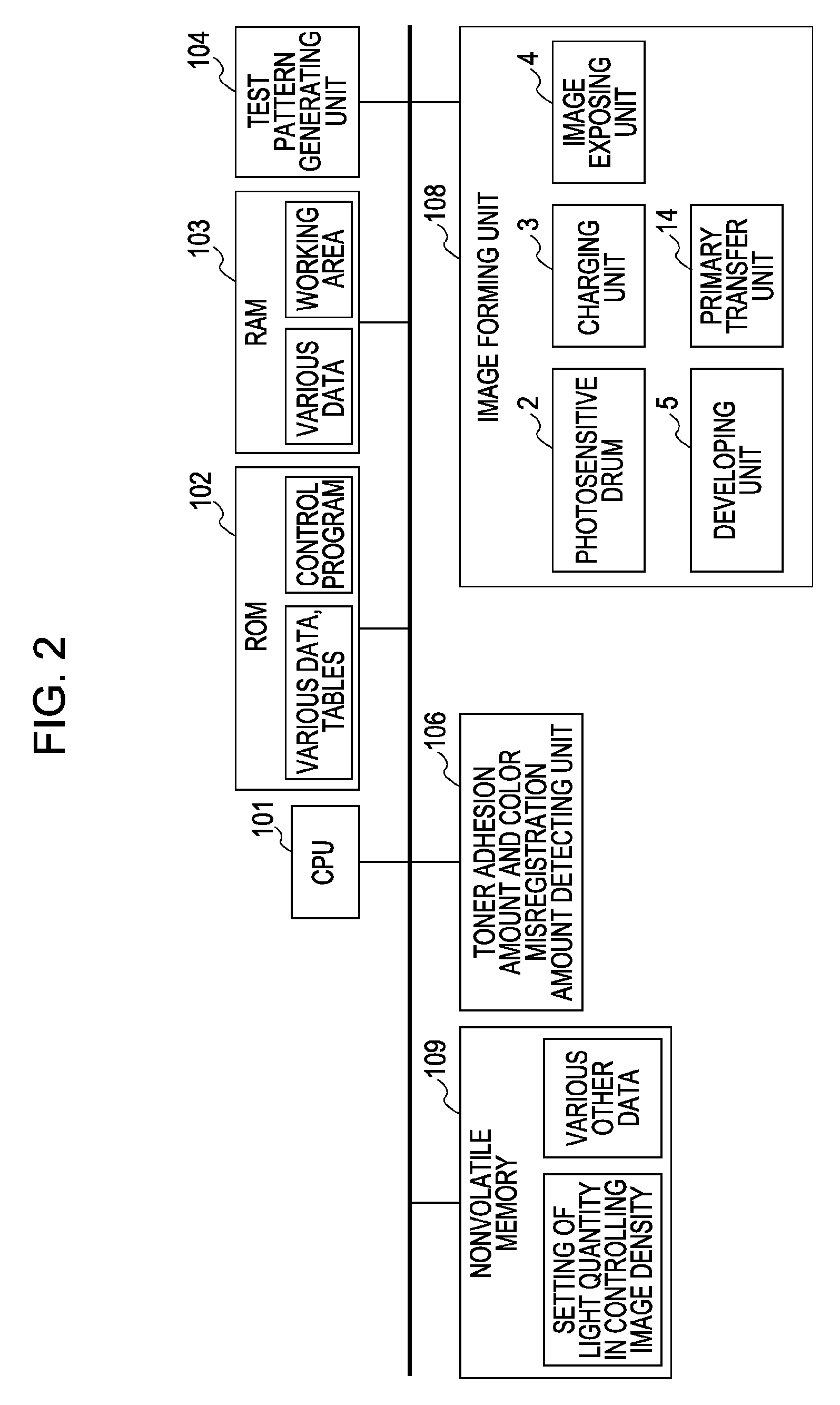
[0121]However, in a further case, for example, lot variations of the optical detecting sensor may cause the photodetector 40b that is designed to primarily receive specular reflected light to receive a large amount of irregularly reflected light. In this case, as with the photodetector 40c, when the toner amount is increased, the output of the photodetector 40c may increase (refer to FIG. 25). this further case is hereunder achieved so that a proper light setting ID′ for the image density control can be selected. That is, three outputs, the output for the intermediate transfer member, itself, of the photodetector 40b that receives specular reflected light, the output for a solid image of the photodetector 40b that receives specular reflected light, and the output for a solid image of the photodetector 40c that receives only irregularly reflected light are used to set a proper light quantity for the image density control.

Color-Misregistration Correction Control and Light Quantity Ad...

second embodiment

[0122]Next, a specific example of color-misregistration correction control according to the embodiment will be described with reference to FIG. 24. Steps S61 to S66 according to the embodiment are similar to Steps S41 to S46 according to the

[0123]According to the embodiment, thereafter, when light quantity adjustment patches are formed and outputs thereof are monitored, outputs from both the photodetectors 40b and 40c are obtained (Step S67).

[0124]The subsequent Steps S68 to S73 are similar to Steps S48 to S53 according to the second exemplary embodiment.

Method of Determining Light Quantity for Image Density Control

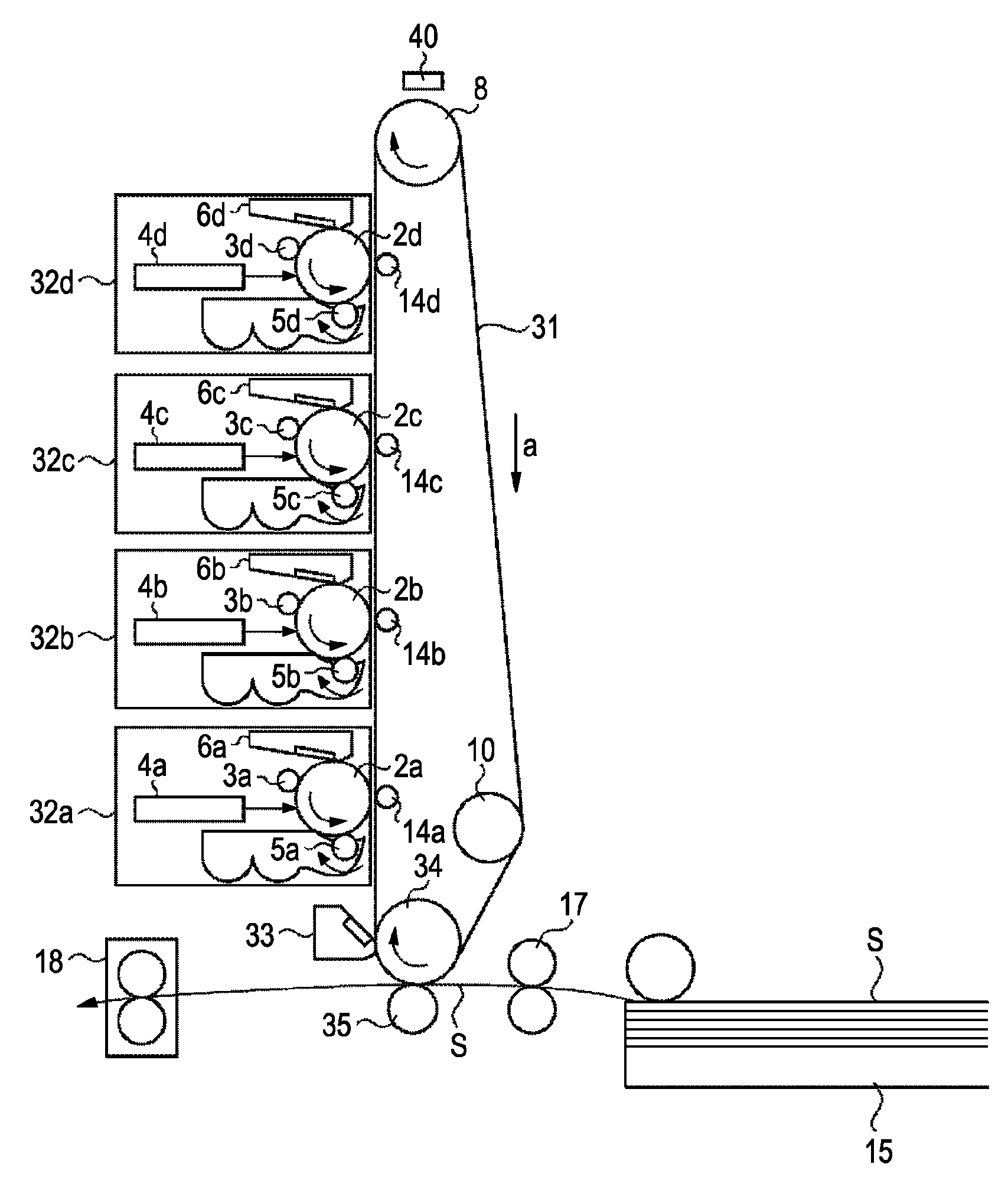
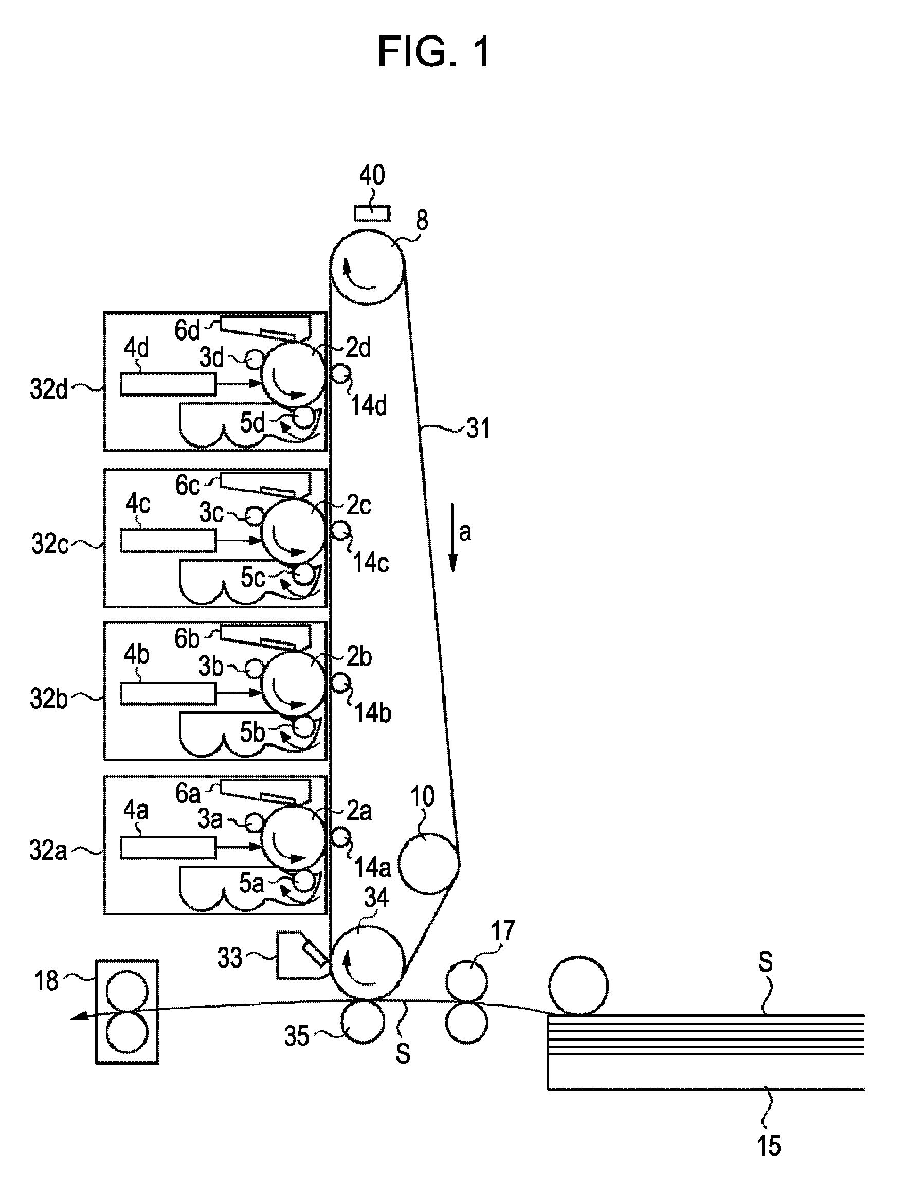
[0125]A following case will hereunder be described. Here, as shown in FIG. 25, when the intermediate transfer belt 31 and patch images are irradiated using the light-emitting element 40a, a maximum output value that is obtained when the yellow (Y), magenta (M), cyan (C), and black (Bk) solid images are detected is larger than an output for the intermediate transfer belt 3...


PUM


Abstract

A color image forming apparatus in which a positional displacement detection image and a light quantity adjustment image are formed within a one-rotation length of an image bearing member (intermediate transfer belt). A light-emission quantity when detecting density is determined on the basis of a detection result of a light quantity adjustment image formed within the one-rotation length using light-emission quantity that is provided when light is emitted to the positional displacement detection image. This allows, for example, image density control to be performed quickly while precision of the image density control is maintained.

Description

BACKGROUND OF THE INVENTION[0001]1. Field of the Invention[0002]The present invention relates to a color image forming apparatus (such as a copying machine, a printer, or a facsimile (FAX)) using an electrophotography method.[0003]2. Description of the Related Art[0004]In recent years, a color image forming apparatus using an electrophotography method is widely used. Since the color image forming apparatus is required to provide precise color reproducibility and color stability, the color image forming apparatus is generally provided with a function for automatically executing image density control. In particular, due to variations in color caused by, for example, changes in the environment in which the color image forming apparatus is used and the history of use of various consumable items, it is necessary to periodically execute the image density control for stabilizing the color at all times.[0005]In an example of the image density control, a plurality of test toner images (patch...

Claims


Application Information

Patent Timeline
Patent Type & Authority Applications(United States)
IPC IPC(8): H04N1/60
CPCG03G15/0131G03G2215/00059G03G15/5058G03G2215/0161G03G2215/0135
Inventor ICHINOSE, KIMITAKAIKEDA, YOSHIMICHINAKAI, TOMOAKIKINUKAWA, TATSUYASEKI, HIROYUKI
Owner CANON KK
Why Eureka
Try Eureka