
Image forming apparatus and method for controlling image density thereof

a technology of image density and forming apparatus, which is applied in the direction of electrographic process apparatus, instruments, optics, etc., can solve the problems of black solid patches consuming a large amount of toner, reducing the sensitivity of sensors, and limited reference test patterns

Inactive Publication Date: 2007-12-13
SHARP KK
View PDF2 Cites 8 Cited by
  • Summary
  • Abstract
  • Description
  • Claims
  • Application Information

AI Technical Summary

Benefits of technology

[0010]In order to solve the above-described problems, the present invention provides an image forming apparatus for stabilizing image densities of a high-density image by devising shapes of test patches, and a method for controlling the image densities of the image forming apparatus.
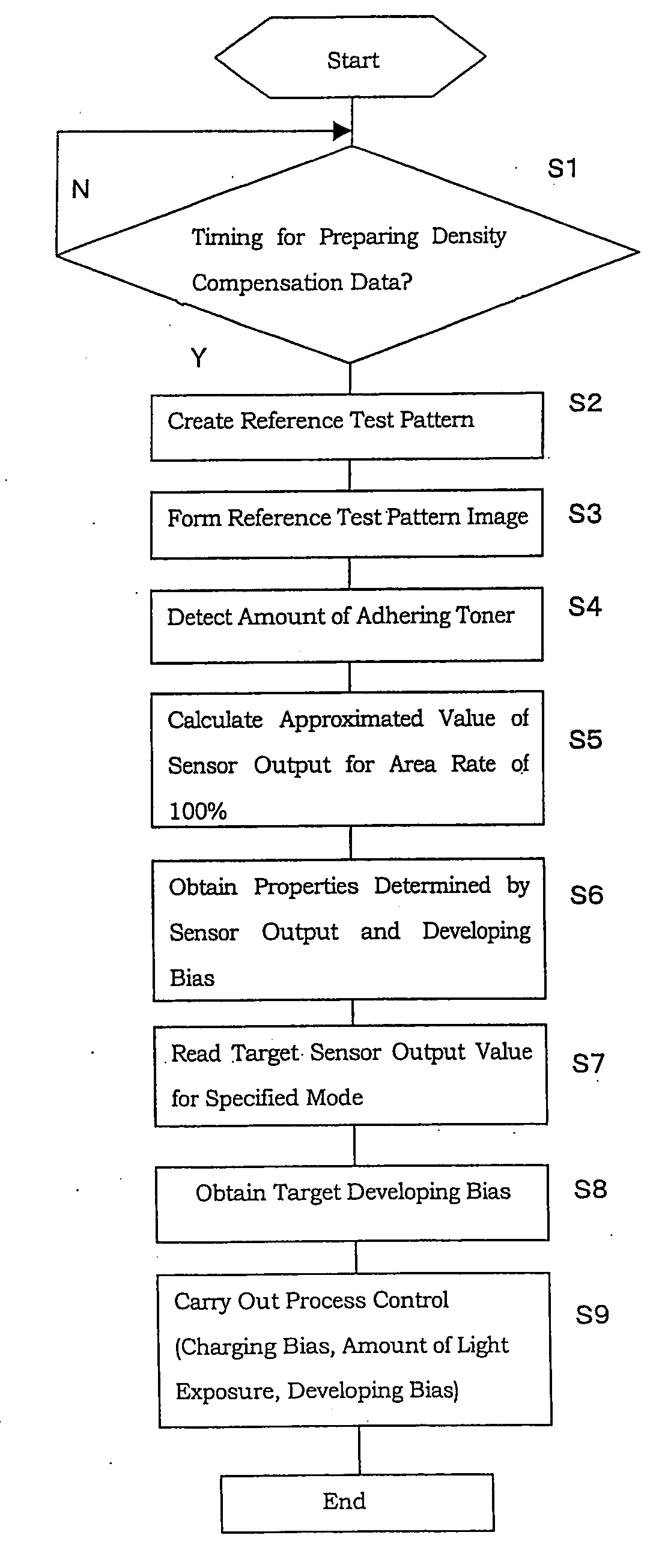
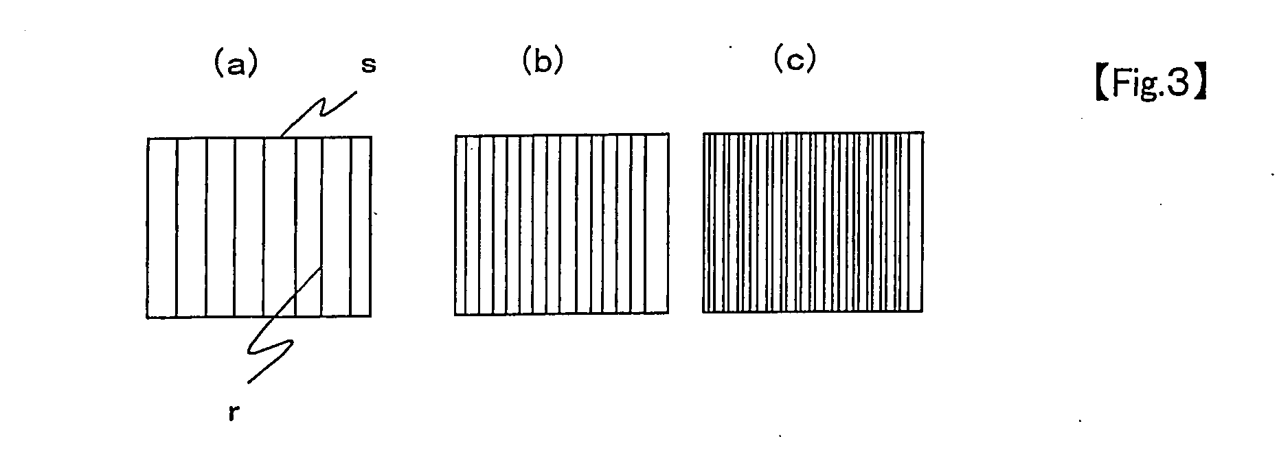
[0011]The present invention provides an image forming apparatus comprising: a test pattern image creation unit for creating a test pattern image by adhering toner to a plurality of test patches having respectively different line area rates of 100% or less; a detection unit for detecting an amount of the toner adhering to the test pattern image; a calculation unit for calculating the amount of the adhering toner for the line area rate of 100%, based on the amount of the adhering toner detected by the detection unit; and a control unit for controlling process conditions so that the amount of the adhering toner obtained by the calculation unit reaches a predetermined value. By doing so, the amount of the adhering toner of a high-density image can be accurately controlled and stabilized. Also, toner consumption can be reduced.
[0012]The image forming apparatus of the present invention is desirable to provide the test patch comprises two or more test patches having respectively different line area rates of 50% or less. By doing so, the amount of the adhering toner can be calculated for the line area rate of 100%. Moreover, since the line area rates are 50% or less, linearity of the amount of the adhering toner and a sensor output of the amount of the adhering toner can be ensured to prevent poor accuracy caused by degradation of the linearity of the sensor output.

Problems solved by technology

When black solid patches are formed, however, the black solid patches absorb light and cause a decrease in sensitivity of a sensor.
Also, the black solid patches consume a larger amount of toners and they are problematic.
Regarding Japanese Unexamined Patent Publication No. 2006-003816, another problem has been identified that kinds of the reference test pattern are limited.

Method used


Image

  • Image forming apparatus and method for controlling image density thereof
  • Image forming apparatus and method for controlling image density thereof
  • Image forming apparatus and method for controlling image density thereof

Examples


Embodiment Construction

[0031]An image forming apparatus of the present invention is adopted for an image forming apparatus such as a copying machine, a printer, a facsimile or a multiple device having those functions to form an image by an electrophotographic process. The image forming apparatus of the present invention is also adopted for a color image forming device and a monochrome image forming device.

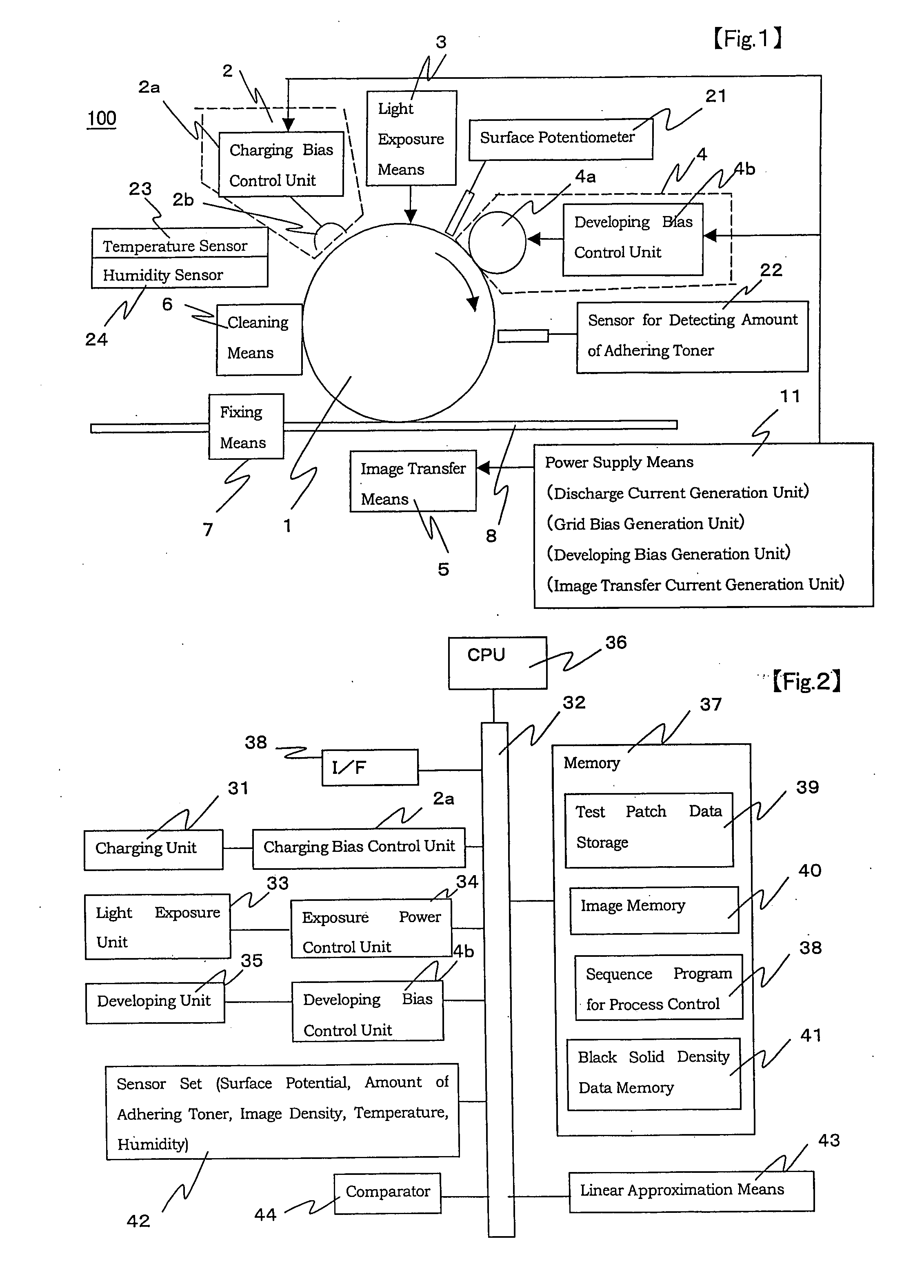
[0032]FIG. 1 is a configuration showing an image forming unit 100 in an image forming apparatus of the present invention. The image forming apparatus comprises a photoconductor 1 and a charging means 2, a light exposure means 3, a developing means 4, an image transfer means 5 and a cleaning means 6 which are peripherally disposed to the photoconductor, and is also provided with a fixing means 7. A recording paper 8 is transported from a sheet feeder (not illustrated) through a delivery path in timing with the image transferred by the image transfer means 5. Toner is then fixed onto the recording paper 8 ...


PUM


Abstract

An image forming apparatus for stabilizing image densities of a high-density image by devising shapes of test patches is provided. A test pattern image is created by adhering toner to a plurality of test patches having respectively different line area rates of 100% or less. An amount of adhering toner for a line area rate of 100% is calculated by detecting the amount of the toner adhering to the test pattern image. Then, process conditions are controlled so that the calculated amount of the adhering toner reaches a predetermined value. By doing so, the amount of the adhering toner of the high-density image is accurately controlled.

Description

CROSS-REFERENCE TO RELATED APPLICATION[0001]This application is related to Japanese Patent Application No. 2006-136746 filed on May 16, 2006, whose priority is claimed and the disclosure of which is incorporated by reference in its entirety.BACKGROUND OF THE INVENTION[0002]1. Field of the Invention[0003]The present invention relates to an image forming apparatus that forms an electrostatic latent image by exposing a surface of a photoconductor with a light beam, visualizes the electrostatic latent image by using toner, and fixes the electrostatic latent image on recording paper by the toner, and a method for controlling an image density of the image forming apparatus. Particularly, the present invention relates to an image forming apparatus that stabilizes the amount of adhering toner or densities of a high-density image.[0004]2. Description of Related Art[0005]In image forming apparatuses, the amount of toner adhering to an image varies depending on the individual apparatuses, a ch...

Claims


Application Information

Patent Timeline
Patent Type & Authority Applications(United States)
IPC IPC(8): G03G13/00
CPCG03G15/5041G03G2215/00042
Inventor MORIKUNI, SHUICHI
Owner SHARP KK
Learn More