
Method for determining linear acceleration and device for its implementation

a linear acceleration and measurement method technology, applied in the field of measuring techniques, can solve the problems of inability to implement absolutely precise leveling of the platform, large errors, and high cost of the accelerometer, and achieve the effect of removing any harmful influen

Inactive Publication Date: 2009-06-11
NAUMOV MICHAEL
View PDF4 Cites 4 Cited by
  • Summary
  • Abstract
  • Description
  • Claims
  • Application Information

AI Technical Summary

Benefits of technology

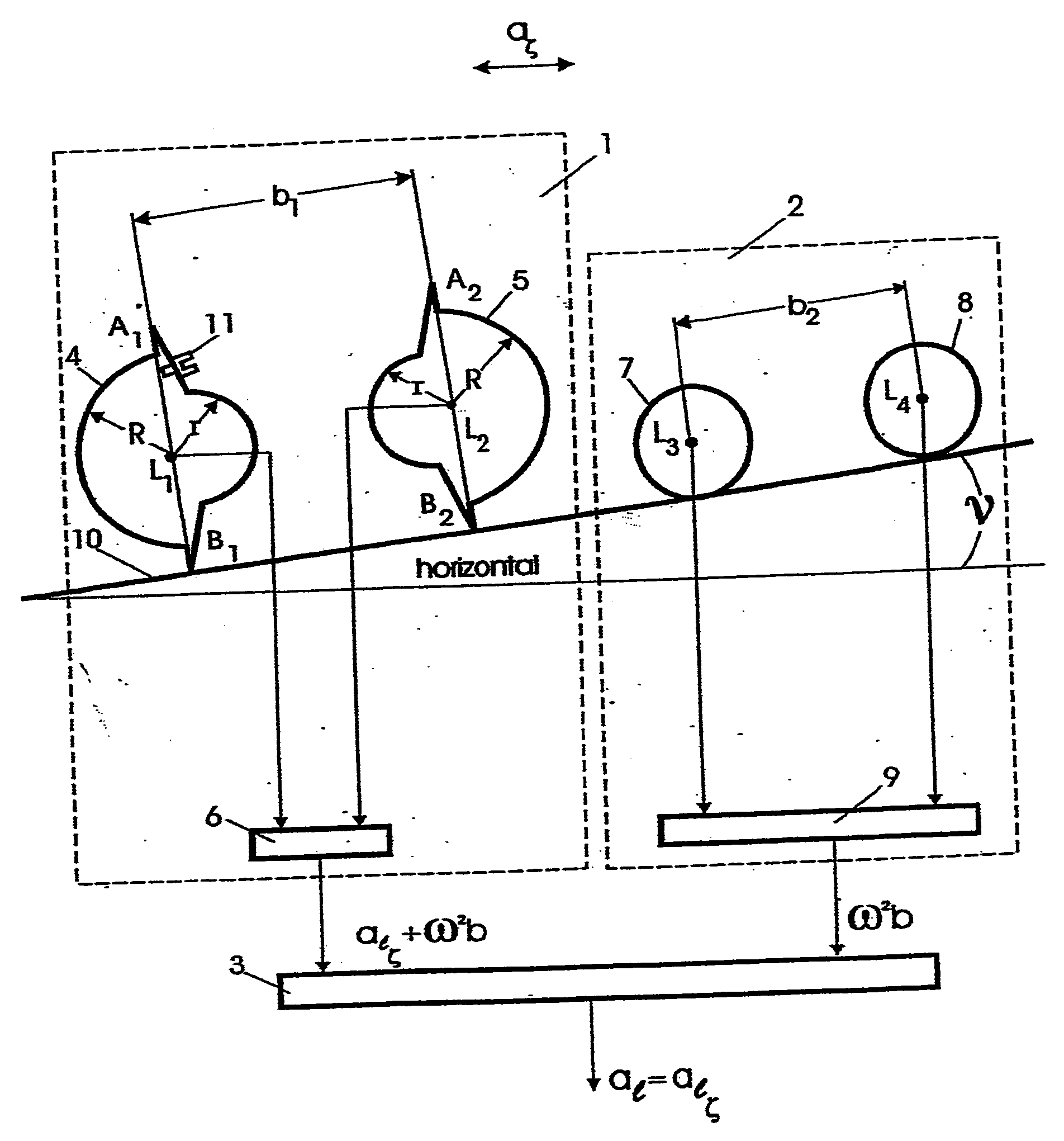
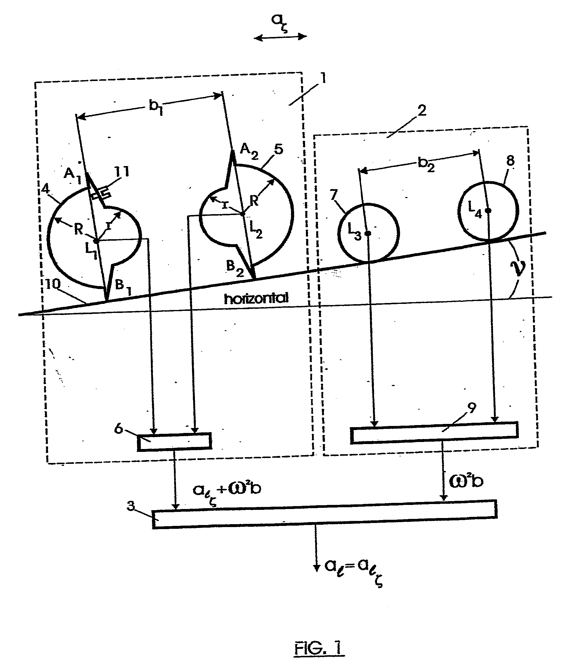
[0047]The authors have found such a ratio between b1 and b2, wherewith any harmful influence of centrifugal (centripetal) accelerations is eliminated.
[0084]Herewith, any harmful influence of not only horizontal but also of any centrifugal (centripetal) accelerations is eliminated, including those occurring due to the rotation of the Earth and the rotation of the moving object around the Earth's center.

Problems solved by technology

Owing to the above, while tilting their axes of sensitivity from the axis along which the measurement of acceleration is made (in particular, a horizontal or vertical axis) there occur major errors being impermissible.
Said errors are caused by the action of cross-axis accelerations (in particular, vertical acceleration when measuring horizontal acceleration or horizontal acceleration when measuring vertical acceleration).
For decreasing said errors, said accelerometers are located on a complicated, expensive, heavy and bulky stabilized (in a horizontal plane) gyro platform.
In addition to that, said gyro platform possesses other considerable drawbacks and shortcomings as well: a long initial alignment (for an accurate alignment tens of minutes are required), the necessity of using very precise gyroscopes, considerable dependence on the action of vertical acceleration, vibrations and others.
However, it is impossible to implement absolutely precise leveling of said platform.
And although said tilting is minor, its harmful influence is considered to be rather noticeable, since the output signal from the accelerometers is usually integrated.
In this case, due to integration of the apparent acceleration when determining horizontal distance or the altitude of a flight, as well as the depth of sinking in water, there occurs an accumulation error being approximately equal to 300 m per every minute of work, which is unacceptable.
However, both in said accelerometer and in said devices [1], [2], [3] there occurs an error caused by the action of centrifugal (centripetal) accelerations.
When the moving object is being rotating, by itself or around any instantaneous center of the rotation, above error can be intolerably big.
For eliminating said error the use of azimuth stabilization is required, which makes the construction considerably more complicated, and thus, increases its weight, cost and sizes.
Moreover, the azimuth stabilization does not fulfill its function even in a straight and level flight, it being because of centrifugal (centripetal) accelerations occurring due to the Earth's rotation and the rotation of a flying vehicle around the Earth's center, when moving in the Earth's sphere.
This harmful influence is especially noticeable when determining the altitude of a flight.
In this case, even with the strict location of the axis of sensitivity of measuring vertical acceleration (along a vertical), because of integration, there occurs an accumulation error in determining the altitude of the flight being equal to approximately 10 m per every minute of the flight, which is unacceptable as well.

Method used


Image

  • Method for determining linear acceleration and device for its implementation
  • Method for determining linear acceleration and device for its implementation
  • Method for determining linear acceleration and device for its implementation

Examples


Embodiment Construction

[0089]Determination of linear acceleration (vector whereof being at a tangent to a trajectory of movement of a moving object) is based on determining of the projection of said vector on each of three chosen mutually perpendicular axes. Said projection is called axial linear acceleration.

[0090]The provided method for determining axial linear acceleration on the chosen axis comprises the following mutually connected stages:[0091]determining axial acceleration consisting of axial linear acceleration and axial differential centrifugal acceleration,[0092]determining said axial differential centrifugal acceleration,[0093]determining said axial linear acceleration by the difference of said axial acceleration and said axial differential centrifugal acceleration.

[0094]By way of an example, in the present application consideration is given to the determination of axial linear acceleration along a horizontal axis denoted by the letter ζ (called a horizontal transverse axis).

[0095]The device im...


PUM


Abstract

The present technical solution for determining linear acceleration, the vector whereof is considered to be at a tangent to a trajectory of movement of a moving object, is based on determining new differences of accelerations. It is considered to be the basis for efficient, accurate, with the threshold of sensitivity equal to zero in small-size option solving the tasks of autonomous navigation, piloting, stabilization and etc. Said solution is irrespective of disturbance factors, in particular, cross-axis and centrifugal accelerations, vibrations, temperature and others, and can be used without any gyroscopes.

Description

FIELD OF THE INVENTION[0001]The present technical solution relates to measuring technique and can be used in the systems of stabilization of movement of transport means—vehicles (ground, air and sea); for navigation, piloting, ship navigation and other purposes.BACKGROUND OF THE INVENTION[0002]For determining acceleration use is made of accelerometers. The accelerometers are considered to measure so-called apparent acceleration. Owing to the above, while tilting their axes of sensitivity from the axis along which the measurement of acceleration is made (in particular, a horizontal or vertical axis) there occur major errors being impermissible. Said errors are caused by the action of cross-axis accelerations (in particular, vertical acceleration when measuring horizontal acceleration or horizontal acceleration when measuring vertical acceleration).[0003]For decreasing said errors, said accelerometers are located on a complicated, expensive, heavy and bulky stabilized (in a horizontal...

Claims


Application Information

Patent Timeline
IPC IPC(8): G01C19/00
CPCG01P3/16G01P15/18G01P15/00
Inventor NAUMOV, MICHAELNAUMOV, GEORGE
Owner NAUMOV MICHAEL
Learn More