Metering valve

a technology of metering valve and valve stem, which is applied in the direction of liquid dispensing, packaging, transportation and packaging, etc., can solve the problems of valve stem not being able to return to an initial closed position, total release or dispensing of the entire product contents, and valves have a tendency to “throttle”

Active Publication Date: 2009-06-11
SUMMIT PACKAGING SYST
View PDF16 Cites 8 Cited by
  • Summary
  • Abstract
  • Description
  • Claims
  • Application Information

AI Technical Summary

Benefits of technology

[0015]The present invention utilizes a contiguous double wall structure including an inner wall defining the metering chamber and an outer wall which defines a crimping and support wall against which the inner rim of the mounting cup of the container can be crimped. The importance of the connected inner and outer walls is that the outer wall may be maintained at the same diameter and thickness for use with generally any mounting cup which are approximately an inch in diameter as well as any mounting process and machinery. The inner wall may however be sized differently in order to accommodate different dosages for metering of product. Importantly there is a radial space between the inner and outer wall which permits the both the axial elongation of the metering chamber as well as a radial expansion of the inner wall and hence the valve chamber relative to the outerwall due to the space between the inner and outer wall.
[0016]Addit

Problems solved by technology

A drawback associated with prior art metering valves is that such valves have a tendency to “throttle”.
That is, due to a poor or an improper valve design, it is possible for an operator to partially depress the valve stem and establish a product flow path from the interior cavity of the aerosol container through the metering valve and out through a spray button or actuator affixed to the stem of the aerosol valve, prior to the valve stem sealing the inlet to the valve housing, so that product may be continuously discharged out through the aerosol valve.
Also, insufficient return force, or pre-load, on the valve spring can cause failure of the valve stem to return to an initial closed position after initial depression.
Failure to observe these manufacturing tolerances, pre-load and alignment criteria leads to an inaccurate metered spray or a valve which will not “shut-off” and thus result in the total release or dispensing of t

Method used


Image

  • Metering valve
  • Metering valve
  • Metering valve

Examples


Embodiment Construction

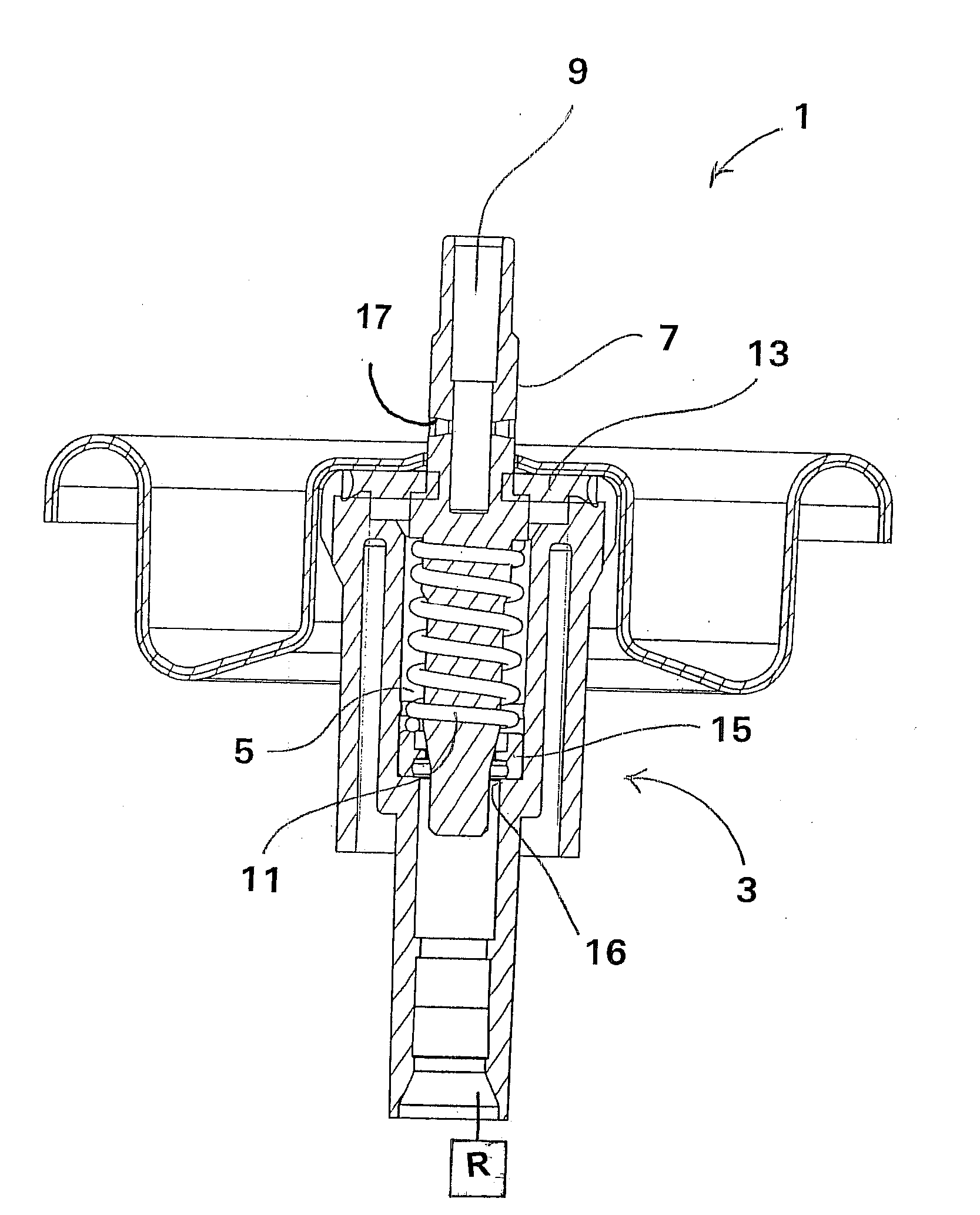
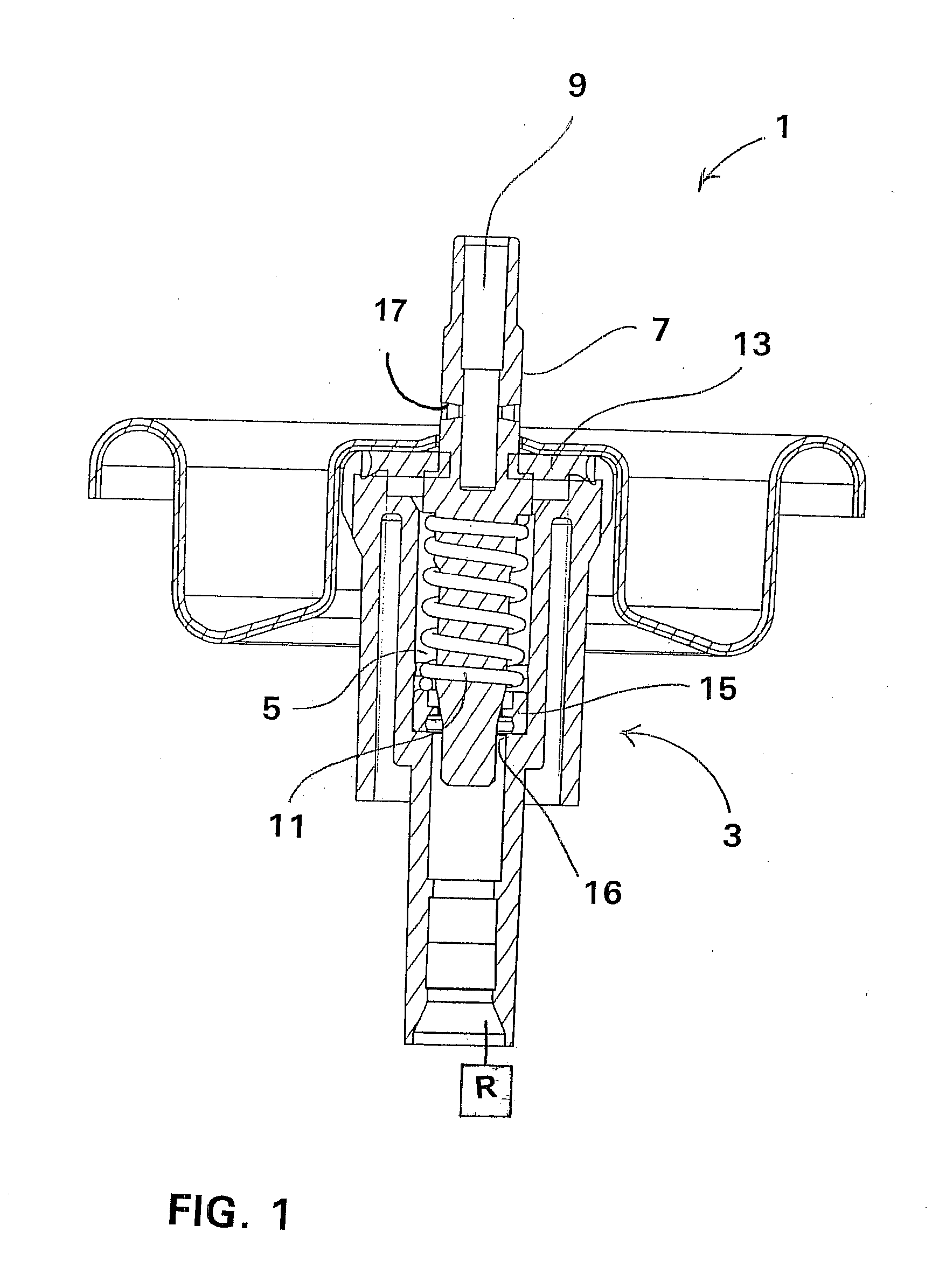
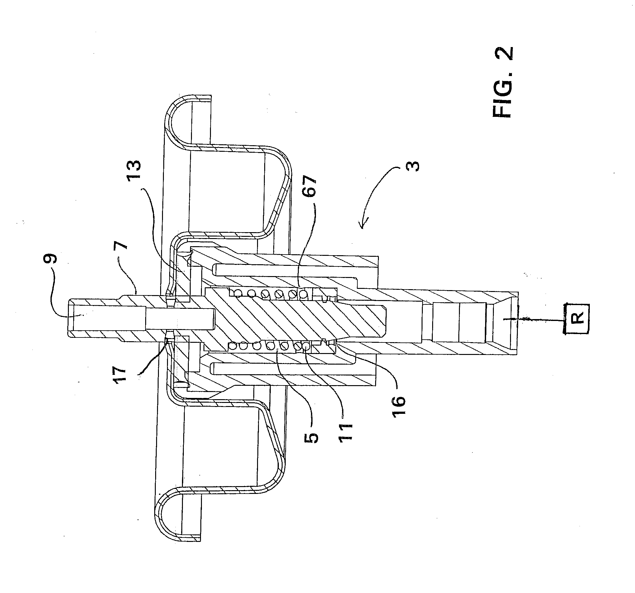
[0024]FIGS. 1-3 show a metering valve 1 of the present invention for a product which is pressurized within a main reservoir R of a container or can (not shown). In general, the metering valve 1 includes a valve body 3 defining a valve chamber 5, a valve stem 7 having a main passageway 9 for expelling the pressurized product from the metering valve 1 chamber, and a valve spring 11 for biasing the valve stem 7 against an upper gasket 13 of the metering valve 1. Also, a seal ring 15 is positioned at the bottom of the metering valve 1 chamber adjacent a product inlet 16 to the valve chamber 5 and surrounding the valve stem 7 in order to prevent passage or leakage of product from the inlet into the valve chamber 5 when the valve is in a product dispensing state.

[0025]The valve works in the following manner, with the seal ring 15 inserted into the valve chamber 5, the valve spring 11, generally a compression spring, sits on a top surface 47 of the seal ring 15 and, according to a desired ...


PUM


Abstract

A metering valve having a contiguous double wall structure including an inner wall defining the metering chamber and an outer wall which defines a crimping and support wall against which the inner rim of the mounting cup of the container can be crimped. The outer wall may be maintained at the same diameter and thickness for use with generally any mounting cup which are approximately an inch in diameter as well as any mounting process and machinery. The inner wall may however be sized differently in order to accommodate different dosages for metering of product. A radial space between the inner and outer wall permits the both the axial elongation of the metering chamber as well as a radial expansion of the inner wall and hence the valve chamber relative to the outer wall due to the space between the inner and outer wall.

Description

FIELD OF THE INVENTION[0001]This invention relates to a metering valve for dispensing a pressurized product, generally an aerosolized liquid from a spray can type container where a discrete, metered dosage is dispensed each time a user actuates the metering valve.BACKGROUND OF THE INVENTION[0002]Metering valves for spray cans are readily available in the marketplace which are constructed to allow a discrete, or pre-proportioned amount of product to be dispensed at each actuation of the valve control push-button. Such metering valves generally comprise a valve body which is associated in a sealed relationship with the mounting cup of the container or can by means of a folded seam or crimped collar. Within the valve body is defined a valve chamber in which an axially slidable valve stem is pushed down by a user against the bias of a valve spring.[0003]Inside the valve chamber there is generally a lower inlet which may include a ring seal adjacent the inlet, where the ring seal is adap...

Claims


Application Information

Patent Timeline
IPC IPC(8): B65D83/06
CPCB65D83/546B65D83/54
Inventor DAVIDEIT, DANIEL E.VERVILLE, KEVIN G.
Owner SUMMIT PACKAGING SYST
Why Eureka
Try Eureka