
Imaging apparatus with autofocus function, imaging method, storage medium, and integrated circuit

a technology of imaging apparatus and function, applied in the direction of instruments, printers, cameras, etc., can solve the problem that the imaging apparatus only has a limited capability of detecting in-focus positions, and achieve the effect of maximizing the optical path length

Inactive Publication Date: 2009-06-11
PANASONIC CORP
View PDF2 Cites 8 Cited by
  • Summary
  • Abstract
  • Description
  • Claims
  • Application Information

AI Technical Summary

Benefits of technology

[0020]The imaging method has the same advantageous effects as the imaging apparatus of the first aspect of the present invention.
[0021]A fifth aspect of the present invention provides a storage medium storing a program that enables a computer to implement an imaging method used in an imaging apparatus including an optical system that focuses light from a subject and over which focus control is executed, an optical path separation unit that separates the light from the subject focused by the optical system into at least a first light beam and a second light beam, a first imaging unit that includes an image sensor, and converts the first light beam to an electric signal and outputs the electric signal as a first signal, a second imaging unit that includes an image sensor, and converts the second light beam to an electric signal and outputs the electric signal as a second signal, and an optical-path length changing unit that changes an optical-path length of the second light beam by moving the second imaging unit along an optical axis of the second light beam. The imaging method includes a control process and an imaging-purpose signal generation process.
[0022]In the control process, a contrast evaluation value of the second signal output from the second imaging unit is generated while the optical-path length of the second light beam is changed by moving the second imaging unit along the optical axis of the second light beam, and an optical-path length of the second light beam corresponding to a maximum contrast evaluation value is detected as a contrast-evaluation-value maximizing optical-path length, and focus control is executed over the optical system based on the contrast-evaluation-value maximizing optical-path length and focus-state information indicating an in-focus state is output. In the imaging-purpose signal generation process, a video signal for imaging-purpose is generated using the first signal and the second signal when the focus-state information indicates an in-focus state, and a video signal for imaging-purpose is generated using the first signal and without using the second signal when the focus-state information indicates an out-of-focus state.
[0023]The storage medium storing the program that enables a computer to execute the imaging method has the same advantageous effects as the imaging apparatus of the first aspect of the present invention.
[0024]A sixth aspect of the present invention provides an integrated circuit used in an imaging apparatus including an optical system that focuses light from a subject and over which focus control is executed, an optical path separation unit that separates the light from the subject focused by the optical system into at least a first light beam and a second light beam, a first imaging unit that includes an image sensor, and converts the first light beam to an electric signal and outputs the electric signal as a first signal, a second imaging unit that includes an image sensor, and converts the second light beam to an electric signal and outputs the electric signal as a second signal, and an optical-path length changing unit that changes an optical-path length of the second light beam by moving the second imaging unit along an optical axis of the second light beam. The integrated circuit includes a control unit and an imaging-purpose signal generation unit.
[0025]The control unit generates a contrast evaluation value of the second signal output from the second imaging unit while changing the optical-path length of the second light beam by moving the second imaging unit along the optical axis of the second light beam, and detects, as a contrast-evaluation-value maximizing optical-path length, an optical-path length of the second light beam corresponding to a maximum contrast evaluation value, and executes focus control over the optical system based on the contrast-evaluation-value maximizing optical-path length and outputs focus-state information indicating an in-focus state. The imaging-purpose signal generation unit generates a video signal for imaging-purpose using the first signal and the second signal when the focus-state information indicates an in-focus state, and generates a video signal for imaging-purpose using the first signal and without using the second signal when the focus-state information indicates an out-of-focus state.

Problems solved by technology

In this case, the imaging apparatus has only a limited capability in detecting an in-focus position because the imaging apparatus is required to minimize effects of the in-focus position detection on a video signal.

Method used


Image

  • Imaging apparatus with autofocus function, imaging method, storage medium, and integrated circuit
  • Imaging apparatus with autofocus function, imaging method, storage medium, and integrated circuit
  • Imaging apparatus with autofocus function, imaging method, storage medium, and integrated circuit

Examples


first embodiment

1.1 Structure of the Imaging Apparatus

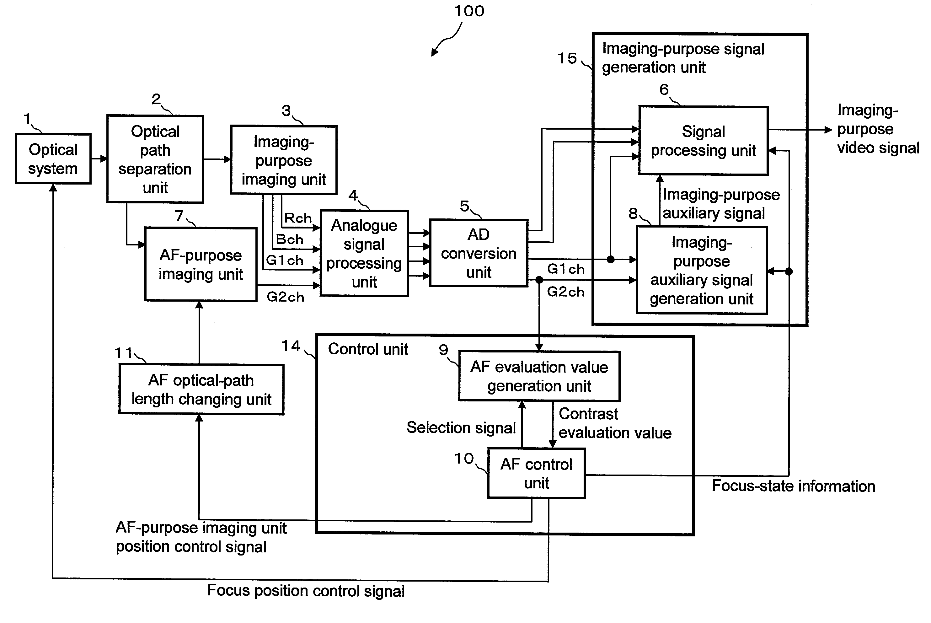
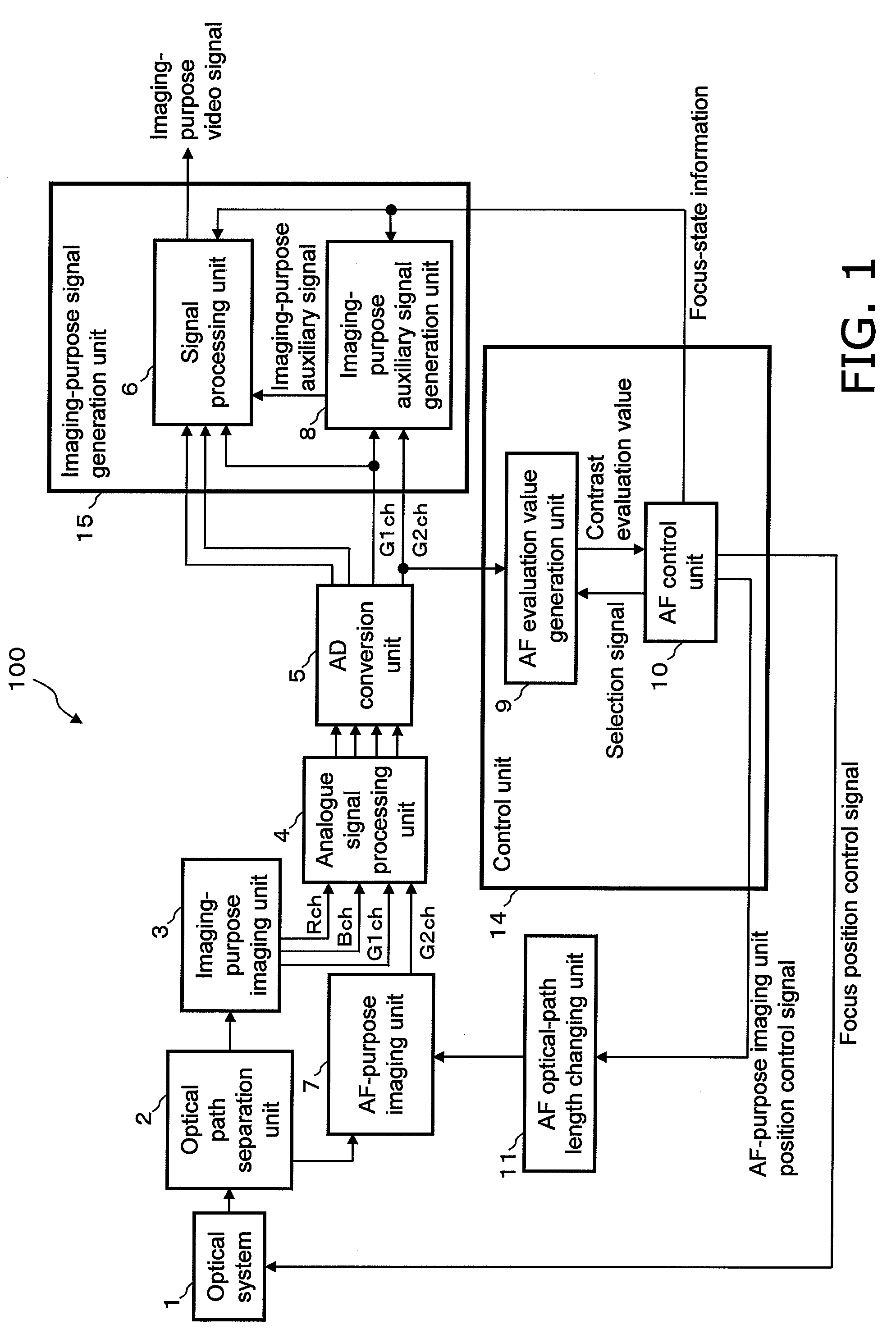
[0055]FIG. 1 is a block diagram showing the structure of an imaging apparatus 100 with an AF function according to a first embodiment of the present invention.

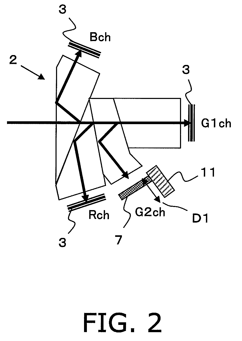
[0056]As shown in FIG. 1, the imaging apparatus 100 with the AF function includes an optical system 1, an optical path separation unit 2, an imaging-purpose imaging unit 3, an analogue signal processing unit 4, an AD conversion unit 5, an imaging-purpose signal generation unit 15, an AF-purpose imaging unit 7, a control unit 14, and an AF optical-path length changing unit 11.

[0057]The optical system 1 focuses light from a subject, and can adjust the focal length (focus position) of the light (light beam) from the subject. In other words, focus control can be executed over the optical system 1. Focus control over the optical system 1 is executed based on a focus position control signal output from the control unit 14. The optical system 1 outputs the focused light (light beam) from the sub...

second embodiment

2.1 Structure of the Imaging Apparatus

[0119]FIG. 6 is a block diagram showing the structure of an imaging apparatus 200 with an AF function according to a second embodiment of the present invention. The imaging apparatus 200 of the present embodiment differs from the imaging apparatus 100 of the first embodiment only in the position at which an image sensor of its AF-purpose imaging unit 12 is arranged and a signal processing method used by its signal processing unit 13. More specifically, the imaging apparatus 200 differs from the imaging apparatus 100 only in that an image sensor for G2 included in the AF-purpose imaging unit 12 is fixed at a position optically completely equivalent to the position at which an image sensor for G1 included in an imaging-purpose imaging unit 3 is arranged, and in that the signal processing unit 13 uses, in an in-focus state, a signal processing method of generating an imaging-purpose video signal after adding together an imaging-purpose auxiliary si...


PUM


Abstract

An imaging apparatus executes AF control without affecting a video signal and prevents video signal qualities in an in-focus state from decreasing. An optical path separation unit 2 separates light from a subject into first and second light beams. A first imaging unit 3 generates a first signal using the first beam. A second imaging unit 7 generates a second signal using the second beam. A control unit 14 generates a contrast evaluation value based on the second signal while changing an optical-path length of the second light beam by back-or-fourth moving the AF-purpose imaging unit 7 and detects a maximum contrast evaluation value, and executes focus control over an optical system 1 based on the optical-path length corresponding to the detected value. An imaging-purpose signal generation unit 15 generates an imaging-purpose video signal using only the first signal in an out-of-focus state, and using the first and second signals in an in-focus state.

Description

[0001]This application claims priority to Japanese Patent Application No. 2007-314303 filed on Dec. 5, 2007. The entire disclosure of Japanese Patent Application No. 2007-314303 filed on Dec. 5, 2007, is hereby incorporated herein by reference.BACKGROUND OF THE INVENTION[0002]1. Field of the Invention[0003]The present invention relates to an imaging apparatus with an autofocus function that automatically focuses on a subject, an imaging method, a program, and an integrated circuit.[0004]2. Description of the Related Art[0005]A multiple-sensor structure imaging apparatus using a color-separating prism is one example of a conventional imaging apparatus, such as a video camera. Such an imaging apparatus has a branch optical path from which a light beam is emitted, in addition to optical paths for light beams into which the incident light is split according to colors. To generate a signal that is used to focus an imaging lens, which is mounted on the camera body, the imaging apparatus i...

Claims


Application Information

Patent Timeline
Patent Type & Authority Applications(United States)
IPC IPC(8): G02B27/64G02B27/40
CPCG02B7/38G02B27/1013G02B27/144H04N9/09G02B27/16H04N5/23212H04N9/045G02B27/145H04N23/673H04N23/13
Inventor YAMAGUCHI, ATSUSHI
Owner PANASONIC CORP
Learn More