Liquid Crystal Display Appliance

a technology of liquid crystal display and display device, which is applied in the direction of electric digital data processing, instruments, computing, etc., can solve the problems of heat air inside the housing being overheated, difficult to keep an airflow passage inside the housing, and heat air inside being not efficiently discharged, so as to prevent the temperature rise of heat-susceptible components and effectively dissipate the heat generated within the apparatus

Active Publication Date: 2009-06-11
MAXELL HLDG LTD
View PDF5 Cites 36 Cited by
  • Summary
  • Abstract
  • Description
  • Claims
  • Application Information

AI Technical Summary

Benefits of technology

[0011]To solve the abovementioned problem, the present invention provides a construction where the heat generating circuit board is arranged into an area substantially divided and separated with reinforcement members which extend in the display vertical direction in order to prevent the heat generated by the hea

Problems solved by technology

On the other hand, it becomes difficult to keep an airflow passage inside a housing constituting an outer shape of the liquid crystal display appliance through which air heated by heat generated inside is to be discharged.
As a result, the heat air inside is not efficiently discharged from inside the housing while the liquid crystal display appliance is made thinner, which results in a problem with heat-susceptible components being over heated.
However, the technology disclosed in Japanese Laid-Open Patent Publication No. 2006-189650 requires spaces for the cross flow fan to rotate around the axis

Method used


Image

  • Liquid Crystal Display Appliance
  • Liquid Crystal Display Appliance
  • Liquid Crystal Display Appliance

Examples


Embodiment Construction

[0025]The best mode embodiment form of the present invention will be described in detail with reference to the accompanying drawings.

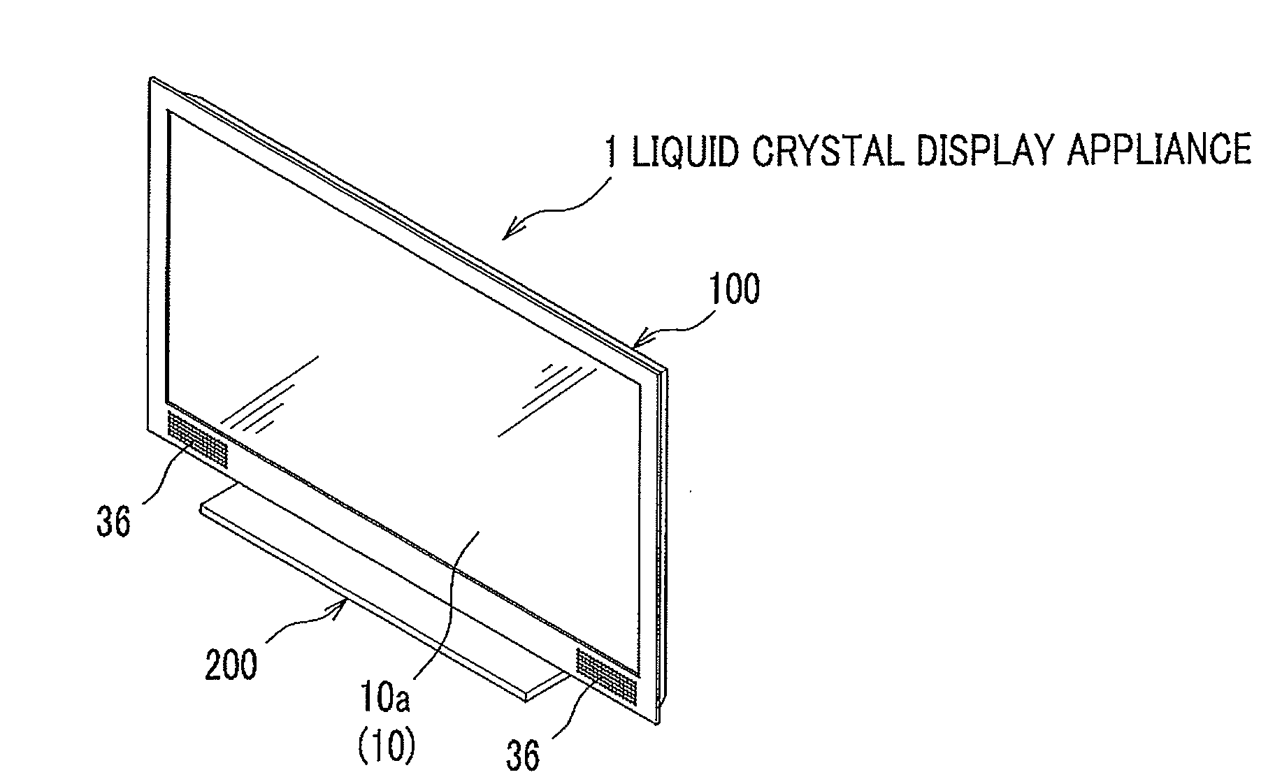
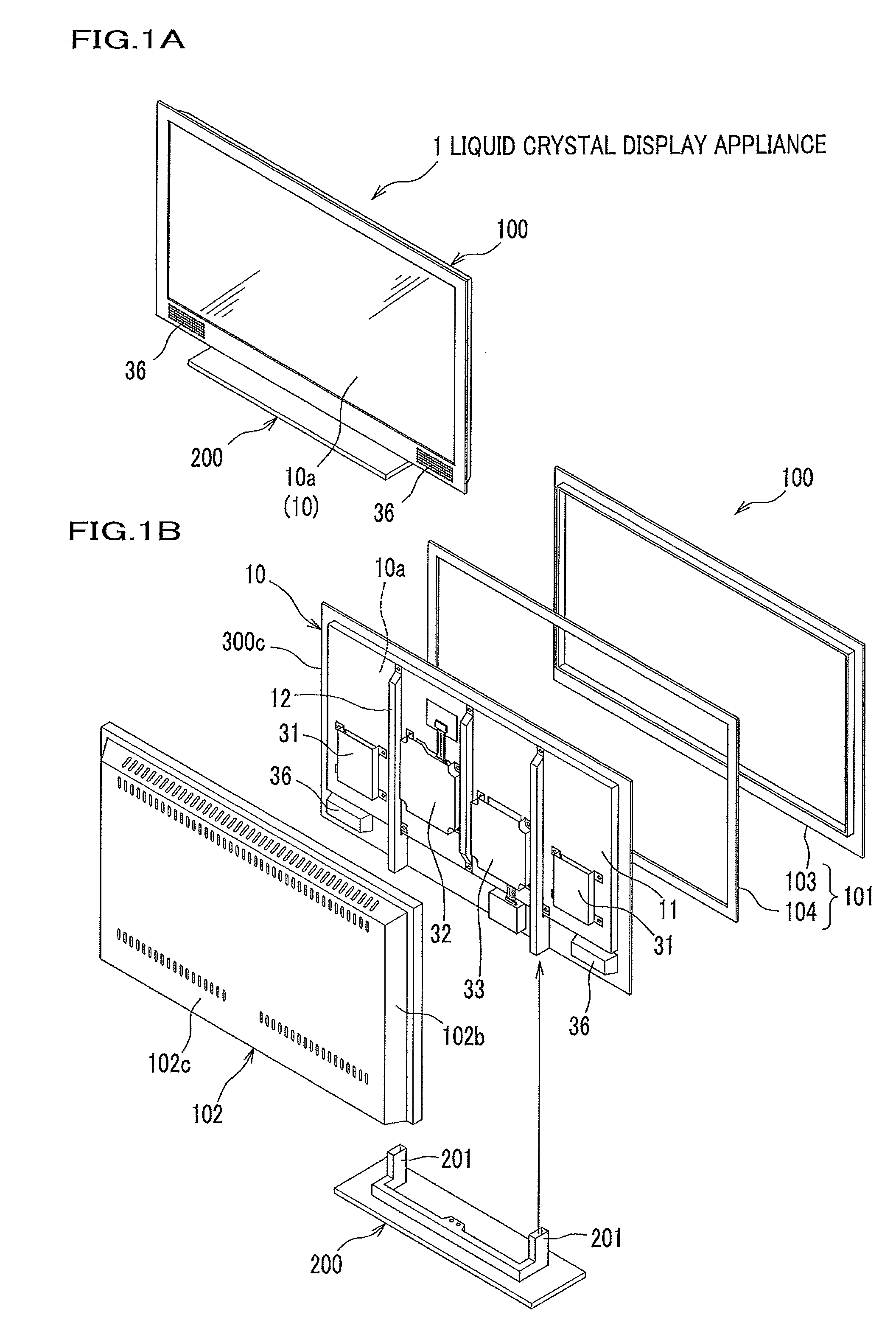
[0026]FIG. 1A is a perspective view showing the liquid crystal display appliance of the present invention. FIG. 1B is an exploded perspective view of the liquid crystal display appliance of the present invention. As shown in FIG. 1A, the liquid crystal display appliance 1 (referred to hereinafter as LCD appliance 1) is a thin type liquid crystal display appliance constituted by a liquid crystal display monitor unit 10 (referred to hereinafter as LCD monitor unit 10) such as a 32 inch size type, for example, a housing 100 to house the LCD monitor unit 10, and a stand 200 which supports the housing 100 from the beneath. The stand 200 is detachable from the housing 100. The LCD appliance 1 can be placed on a floor or on a television set stand (not shown) with the stand 200 is attached. When the stand 200 is detached, the LCD appliance 1 can be hung on a w...


PUM


Abstract

A liquid crystal display apparatus which exhausts heat generated within the apparatus efficiently, and reduces temperature increase in the heat-frail sections is provided.
A circuit board mounting surface at the back of the liquid crystal monitor unit is divided into a plurality of board mount areas using the vertically extending reinforcement members. A signal circuit board section and TCON (Timing control) circuit board section are disposed in the same board mount area which is different from the partition where the power supply circuit board section resides. By arranging this way, the temperature increase in the heat-frail sections of the signal circuit board section is reduced, and the hot air heated by the power supply circuit board in the power supply circuit board section goes up along the reinforcement members, thus an efficient heat exhaustion is achieved.

Description

CROSS REFERENCE TO RELATED ART[0001]The present application claims the benefit under 35 U.S.C. 119 of Japanese Patent Application No. 2007-317028 filed on Dec. 7, 2008, the disclosure of which is incorporated into this application by reference.BACKGROUND OF THE INVENTION[0002]1. Field of the Invention[0003]The present invention relates to a liquid crystal display appliance for efficient dissipation of the heat generated within the apparatus.[0004]2. Description of the Related Art[0005]More and more flat panel display appliances such as plasma display panels of an emissive type and liquid crystal display appliances of a non-emissive type have been recently used in place of conventional Cathode Ray Tube appliances (CRT).[0006]The liquid crystal display appliance utilizes a liquid panel display panel working as an optical modulator of a light transmissive type and a lighting system (referred to as back-light unit) which is attached on the back side of the liquid and emits light to the ...

Claims


Application Information

Patent Timeline
IPC IPC(8): G02F1/1333
CPCG02F2001/133628H05K7/20963G06F1/20G06F1/1601G02F1/133628
Inventor TSUMURA, MAKOTOOHASHI, SHIGEOKAKU, NOBUYUKI
Owner MAXELL HLDG LTD
Why Eureka
Try Eureka