Conference apparatus

a technology of sound pickup and conference equipment, which is applied in the field of sound pickup devices, can solve the problems of difficult to follow the movement of the speaker, the apparatus cannot avoid picking up noise from the noise source, and the difficulty of reducing the level of picked-up sound signals by synthesis, so as to achieve the effect of preventing nois

Active Publication Date: 2009-06-11
YAMAHA CORP
View PDF17 Cites 44 Cited by
  • Summary
  • Abstract
  • Description
  • Claims
  • Application Information

AI Technical Summary

Benefits of technology

[0007]Accordingly, in order to solve the above-described problems, and it is an object of the invention to provide a sound pickup device that can pick up speaking of plural persons at a high level at the same time and, even though there is a noise source in a room, can prevent noise from being picked up, and a voice conference apparatus.

Problems solved by technology

Accordingly, when a noise source exists in a conference room, the apparatus cannot avoid picking up noise from the noise source.
Further, it is impossible to increase levels of the picked-up sound signals by synthesis or the like.
Accordingly, when the speaker moves, it is difficult to follow the movement of the speaker (an attendant in a conference).
As a result, the configuration of the apparatus becomes complex.

Method used


Image

  • Conference apparatus
  • Conference apparatus
  • Conference apparatus

Examples


first embodiment

[0045]A voice conference apparatus according to a first embodiment of the invention will now be described with reference to the accompanying drawings. FIGS. 1 and 2 are diagrams illustrating functional characteristics of a voice conference apparatus.

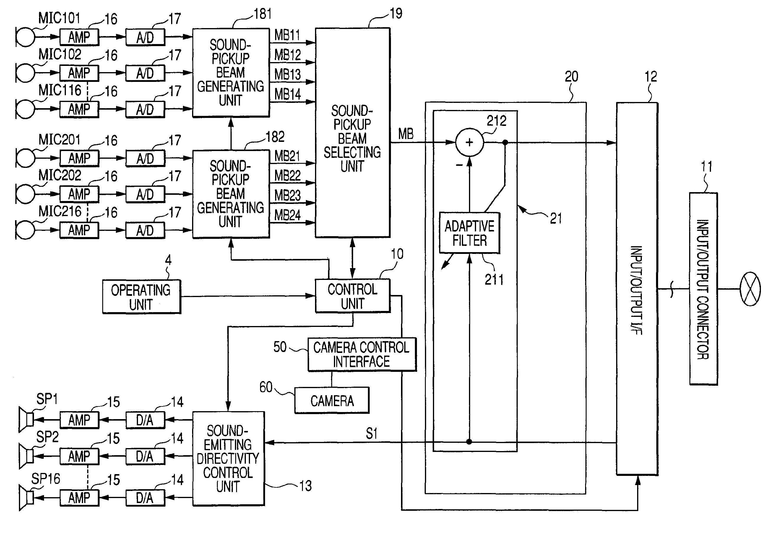
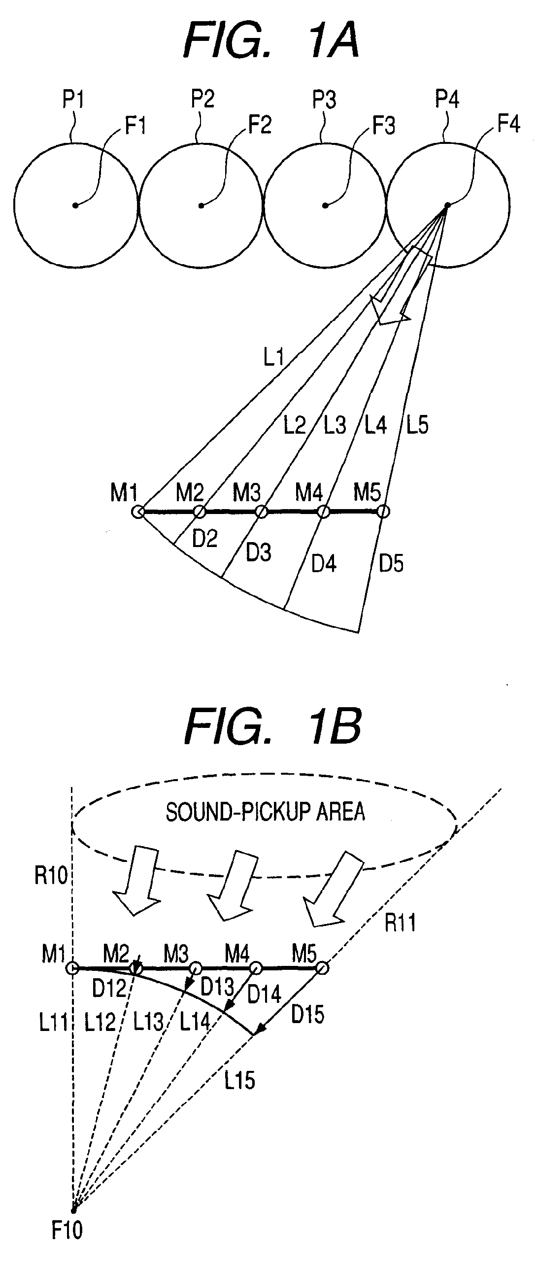
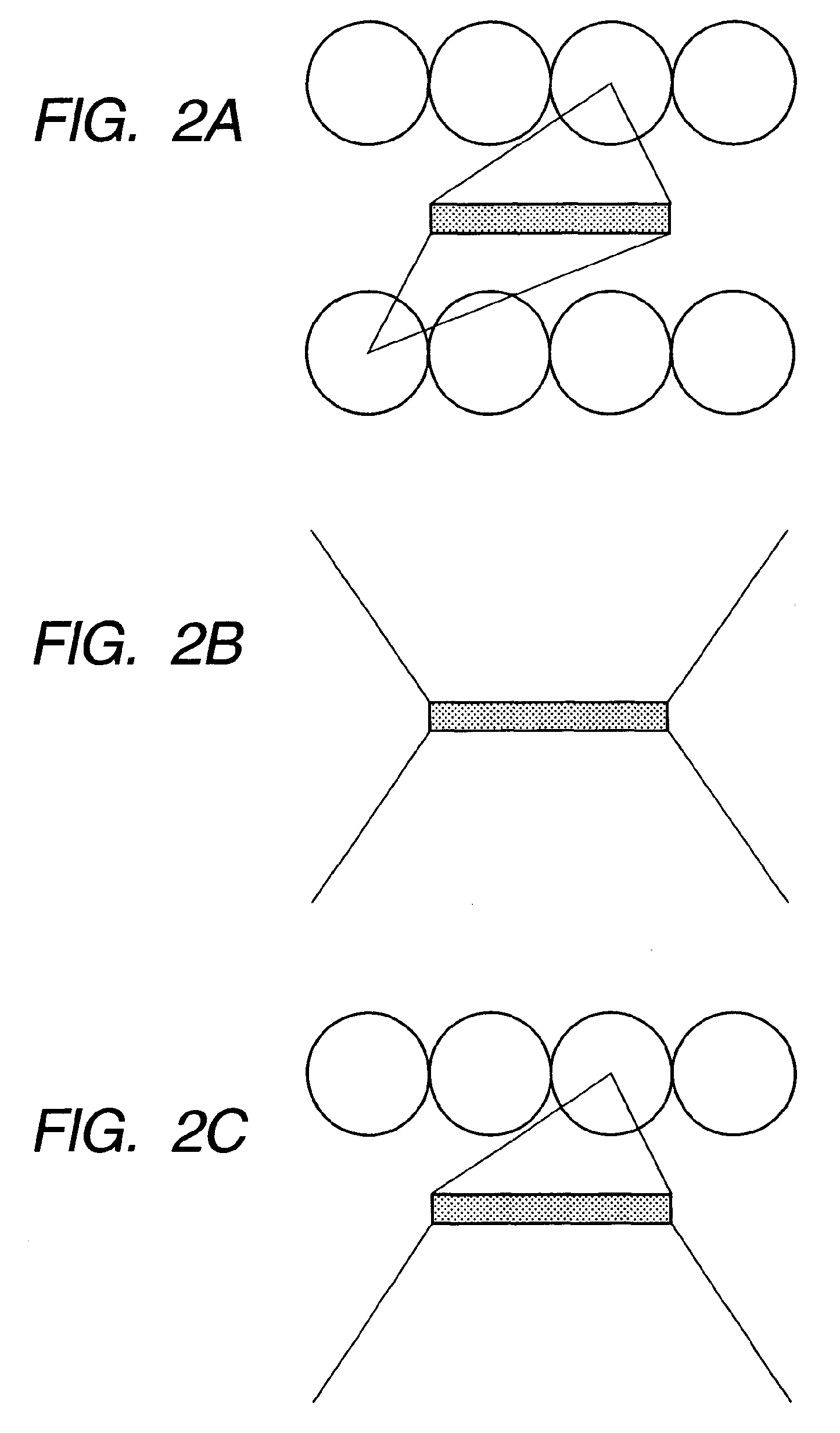
[0046]The voice conference apparatus uses a microphone array including a plurality of microphones that are linearly arranged. The voice conference apparatus delays sound picked up by the individual microphones, and subsequently synthesizes picked up sound, so that sound-pickup directivity of the entire microphone array is controlled to act as a beam. Further, the voice conference apparatus pucks up sound (speaking) generated at a specific spot or area, which is a destination of a sound-pickup beam, at a high gain, and suppresses sound (noise) generated at other areas. In the present application, the beam of the sound-pickup directivity controlled to act as a beam is referred to as the sound-pickup beam.

[0047]In the voice conference appar...

second embodiment

[0094]A second embodiment of the invention is a modification of the first embodiment. In the second embodiment, the same parts as those in the first embodiment are denoted by the same numerals, and thus a description thereof will be omitted.

[0095]The second embodiment is related to a TV conference system in which a camera for capturing an image of the conference room is installed in the voice conference apparatus.

[0096]FIG. 8 is a block diagram showing the configuration of the TV conference system according to the second embodiment. FIG. 9 is a top view showing a conference room where the TV conference system is installed.

[0097]The configuration of the TV conference system according to the second embodiment is different from that of the voice conference apparatus according the first embodiment in that a camera control interface 50 connected to the control unit 10 and a camera 60 for capturing an image of the conference room are installed in the system.

[0098]The camera 60 is arranged...


PUM


Abstract

Microphone arrays, which are formed by arranging a plurality of microphones, are provided on a front side and a rear side of a housing, respectively. A virtual focus is set for each of the microphone arrays in a direction opposite to a direction in which sound is picked-up sound signals picked up by the plurality of microphones are delayed such that distances to the virtual focus are the same, and the delayed sound signals are synthesized. Therefore, sound in a sound-pickup area of a predetermined angle on each of the front side and the rear side can be picked up at a high level, and even though there is a noise source in areas other than the sound-pickup area, noise from the noise source is not picked up.

Description

BACKGROUND ART[0001]The present invention relates to a sound pickup device that picks up sound from a desired area using a microphone array, and to a voice conference apparatus, to which the sound pickup device is applied.[0002]In the past, voice conference apparatuses have been proposed as apparatuses for performing a voice conference among remote places (for example, see Patent Documents 1 and 2). The voice conference apparatus has a function of picking up sound of attendants of a voice conference and transmitting sound to remote voice conference apparatuses.[0003]There are often many attendants in the conference, and thus the voice conference apparatus needs to pick up sound of each attendant at the same level and at a level as high as possible. In addition, when the attendant moves, the voice conference apparatus needs to prevent the attendant from departing from a sound-pickup area despite the attendant's movement. Further, when there is often a noise source, such as a projecto...

Claims


Application Information

Patent Timeline
Patent Type & Authority Applications(United States)
IPC IPC(8): H04R3/00H04M3/42H04N7/14
CPCG10L2021/02087G10L2021/02166H04R1/40G10L21/02H04R3/12H04R3/005H04R1/406H04M9/08
Inventor ISHIBASHI, TOSHIAKITANAKA, RYOUKAI, SATOSHI
Owner YAMAHA CORP
Why Eureka
Try Eureka