Image processing apparatus, image display apparatus, image forming apparatus, image processing method and storage medium

a technology of image processing and display apparatus, applied in the field of image, can solve the problems of reducing affecting the image quality of the image, and requiring longer processing time, so as to prevent the pixel value of the imag

Inactive Publication Date: 2009-06-11
SHARP KK
View PDF15 Cites 42 Cited by
  • Summary
  • Abstract
  • Description
  • Claims
  • Application Information

AI Technical Summary

Benefits of technology

[0029]In the sixth aspect, whether a correction to be made to the pixel value of a pixel near a contour based on the distance from the line segment vector is effective or ineffective is determined based on the inner product of the line segment vector and a vector from the starting point of the line segment

Problems solved by technology

However, since the image is regenerated after calculating smoothed contour vectors and scaling the contour vectors by a desired scale factor, a longer processing time is required.
It is therefore difficult to realize high-speed drawing b

Method used


Image

  • Image processing apparatus, image display apparatus, image forming apparatus, image processing method and storage medium
  • Image processing apparatus, image display apparatus, image forming apparatus, image processing method and storage medium
  • Image processing apparatus, image display apparatus, image forming apparatus, image processing method and storage medium

Examples


embodiment 1

[0058]Embodiment 1 explains an example in which an image processing apparatus according to this embodiment is realized by configuring an integrated circuit (codec circuit), which is designed to perform the process of encoding / decoding an image based on a vector quantization technique, to further execute a resolution conversion (scaling) process using contour vector information as to be explained below.

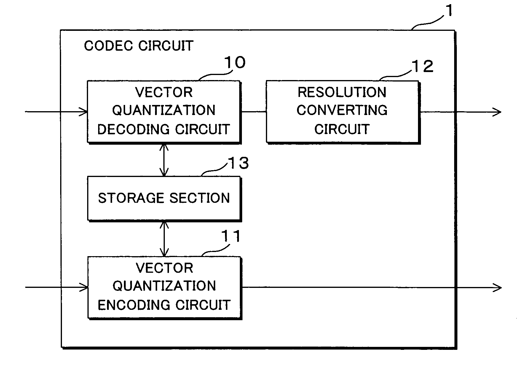
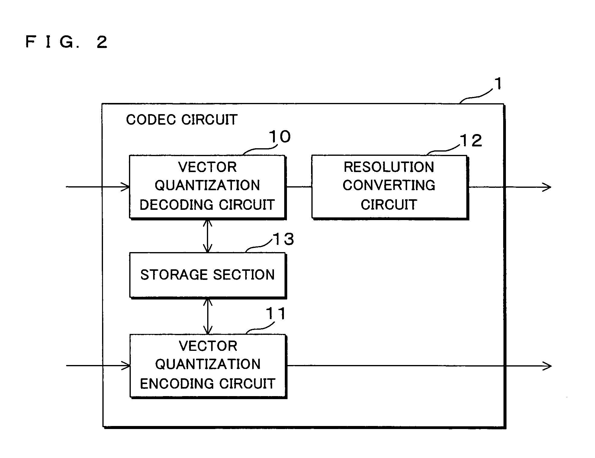
[0059]FIG. 2 is a block diagram showing the structures of a codec circuit of Embodiment 1. A codec circuit 1 comprises a vector quantization encoding circuit 11 for encoding image data by using a vector quantization technique; a vector quantization decoding circuit 10 (decoding means, decoding section) for decoding image data encoded by vector quantization; a resolution converting circuit 12 (scaling means, scaling section, redrawing section) for performing a resolution conversion process; and a storage section 13 for storing various kinds of information for use in vector quantization....

embodiment 2

[0152]Embodiment 2 explains, as an example, a case where this embodiment is applied to a display apparatus which decodes an index image obtained by encoding an image containing characters etc. by using vector quantization, and displays the decoded image. The display apparatus of Embodiment 2 comprises the codec circuit 1 explained in Embodiment 1, decodes an image using the codec circuit 1, scales the image, and displays the image.

[0153]Since the codec circuit 1 included in the display apparatus of Embodiment 2 is the same as the codec circuit 1 of Embodiment 1, the detailed explanation thereof is omitted by assigning the same codes.

[0154]FIG. 23 is a block diagram showing the structure of the display apparatus 2 of Embodiment 2. The display apparatus 2 comprises a microcomputer 200 including a CPU (Central Processing Unit) 20, a ROM 21 and a RAM (Random Access Memory) 22; a codec circuit 1; a cache memory 23; an image memory 24; a display 25; a storage 26; an image display section ...

embodiment 3

[0167]Embodiment 3 explains an example in which this embodiment is applied to an image forming apparatus which decodes an index image obtained by encoding an image containing characters etc. by vector quantization and forms the image on a sheet. The image forming apparatus in Embodiment 3 comprises a codec circuit 1 illustrated in Embodiment 1, and decodes and scales an image by using the codec circuit 1 to form an image.

[0168]Since the codec circuit 1 included in the image forming apparatus of Embodiment 3 is the same as the codec circuit 1 of Embodiment 1, the detailed explanation thereof is omitted by assigning the same codes.

[0169]FIG. 24 is a block diagram showing the structure of an image forming apparatus 3 of Embodiment 3. The image forming apparatus 3 comprises a microcomputer 300 including a CPU 30, a ROM 31 and a RAM 32; a codec circuit 1; a cache memory 33; an image memory 34; a printing control section 35; a communication section 36; and a printer 37 for performing actu...


PUM


Abstract

With the use of a vector quantization technique, an index image, which is obtained by replacing an image on a block-by-block basis, each block consisting of a predetermined number of pixels, with any of a plurality of different pixel patterns and representing the pixel patterns by index values of the respective pixel patterns, is decoded by referring to a code book containing the pixel patterns and the index values of the pixel patterns in association with each other. When decoding an index image on the block-by-block basis into pixel patterns corresponding to the index values, the pixel pattern of each block is scaled, and additionally pixels near a contour in the pixel pattern after scaling are redrawn based on contour vector information corresponding to the pixel pattern.

Description

CROSS-REFERENCE TO RELATED APPLICATION[0001]This non-provisional application claims priority under 35 U.S.C. §119(a) on Patent Application No. 2007-318824 filed in Japan on Dec. 10, 2007, the entire contents of which are hereby incorporated by reference.BACKGROUND[0002]1. Technical Field[0003]The present invention relates to an image processing apparatus for performing compression / encoding and decoding / decompression of image data. In particular, the present invention relates to an image processing apparatus capable of realizing multi-scalable drawing based on image data encoded with a vector quantization technique by high speed processing; an image display apparatus and image forming apparatus incorporating the image processing apparatus; an image processing method; and a storage medium.[0004]2. Description of Related Art[0005]In order to realize efficient transmission and recording of digital images and a reduction of the storage capacity, various techniques for reducing the amount...

Claims


Application Information

Patent Timeline
IPC IPC(8): G06K9/00G06T3/40G06T9/20H04N1/393H04N1/41
CPCG06T9/00G06T9/20G06T9/008H04N19/94
Inventor MATSUDA, TOYOHISA
Owner SHARP KK
Why Eureka
Try Eureka