Apparatus and method for depositing synthetic fibers to form a non-woven web

A technology of synthetic fibers and textile webs, applied in textiles and papermaking, melt spinning, fiber processing, etc., can solve problems such as loss of effectiveness, and achieve the effect of increasing strength

Inactive Publication Date: 2010-01-27
OERLIKON TEXTILE GMBH & CO KG
View PDF6 Cites 7 Cited by
  • Summary
  • Abstract
  • Description
  • Claims
  • Application Information

AI Technical Summary

Problems solved by technology

Although this helps to achieve special effects in the lay-up of nonwoven webs,

Method used


Image

  • Apparatus and method for depositing synthetic fibers to form a non-woven web
  • Apparatus and method for depositing synthetic fibers to form a non-woven web
  • Apparatus and method for depositing synthetic fibers to form a non-woven web

Examples


Embodiment Construction

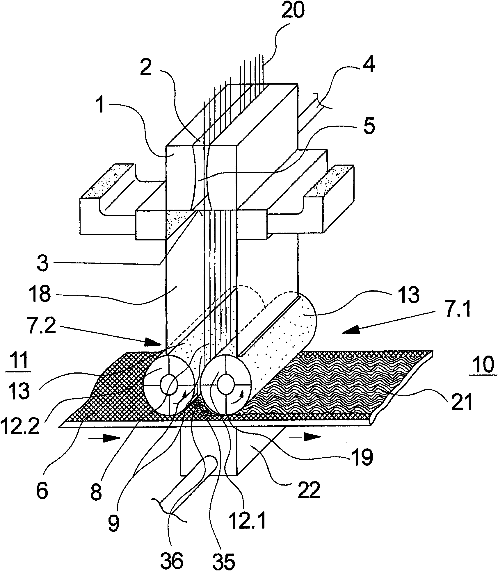
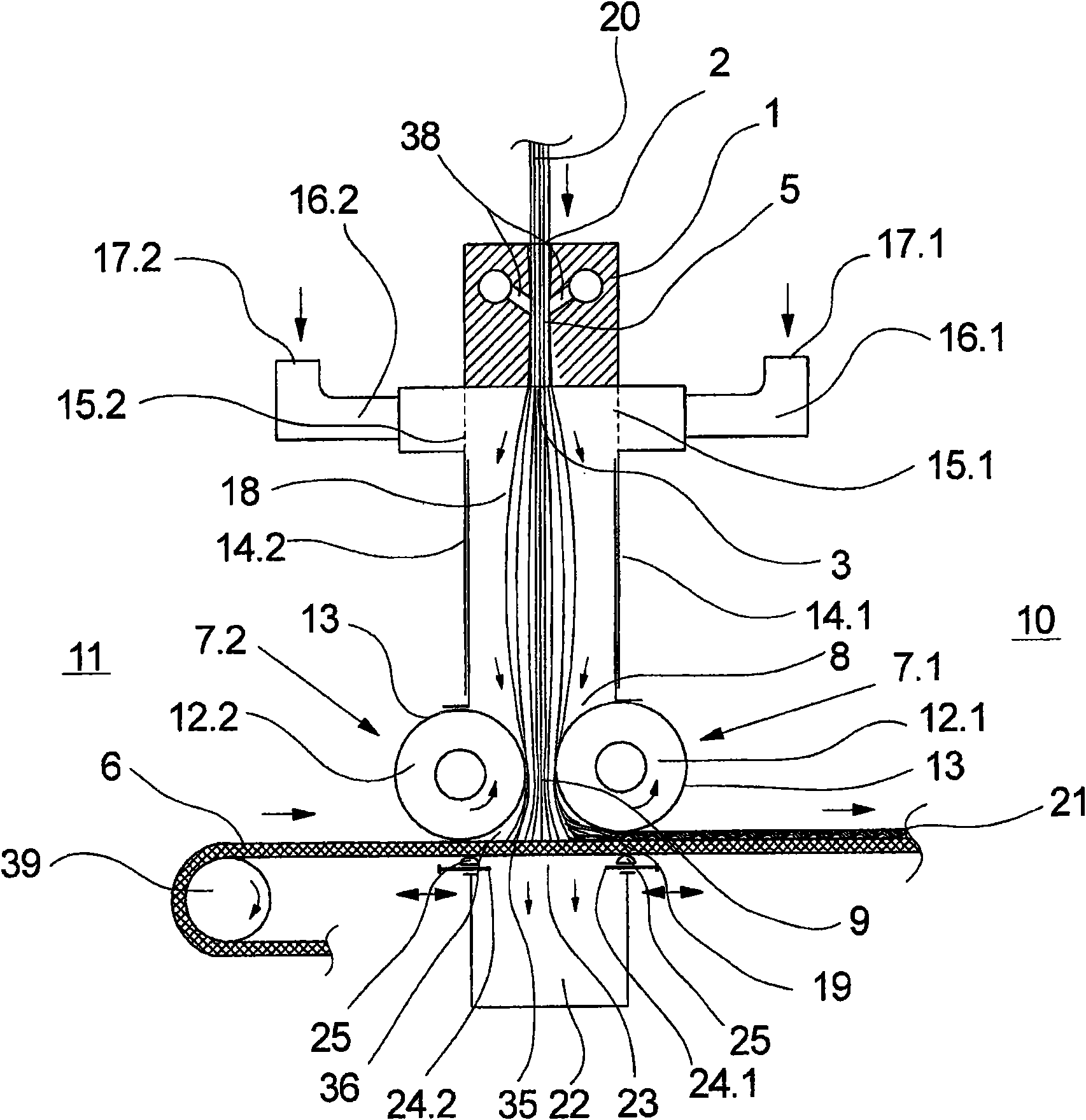
[0037] figure 1 and figure 2 A first exemplary embodiment of the device according to the invention for carrying out the method according to the invention for laying down synthetic fibers to form a nonwoven web is shown schematically. figure 1 shows a side view of the exemplary embodiment while figure 2 A cross-sectional view thereof is schematically shown. The following description applies to both figures unless reference is made to a certain figure.

[0038] figure 1 and figure 2 The exemplary embodiment shown shows a parallelepiped drawing unit 1 which is generally arranged below the spinning arrangement. Pulling units of this type are generally known and described in detail in US patent documents US 6,183,684 B1 or US 7,172,398 B2. In this respect reference is made to the aforementioned publications, only the main parts of which are included below.

[0039] The drawing unit 1 comprises a central conveying channel 5 which is delimited on the upper side of the drawi...


PUM

PropertyMeasurementUnit
Lengthaaaaaaaaaa

Abstract

The invention relates to an apparatus and a method for depositing synthetic fibers to form a non-woven web, in which method the synthetic fibers are guided in the form of a blowing stream through a drawing unit for being deposited on a deposit belt. For this purpose, inside the guidance distance between a blast opening of the drawing unit and the deposit belt, several guidance means are arranged, which form a guidance channel above the deposit belt, wherein the guidance means form a channel opening of the guidance channel at a distance from the blast opening of the drawing unit. In order to achieve constant strength in the deposition of the fiber strands in the non- woven web, the distance between the outlet of the drawing unit and the channel opening of the guidance channel is larger than half the guidance distance according to the invention, wherein the guidance width of an open space formed between the outlet of the drawing unit and the channel opening of the guidance channel is larger than that of the guidance channel.

Description

technical field [0001] The invention relates to a device for depositing synthetic fibers to form a nonwoven web according to the preamble of claim 1 and a device for depositing a plurality of fibers according to the preamble of claim 19 A method of forming a nonwoven web. Background technique [0002] When producing nonwoven webs of synthetic fibers, the plurality of extruded fiber strands must be laid down as evenly as possible to form the fabric. The fiber strands are withdrawn with a feed fluid and directed to a deposit belt, substantially after the extrusion and cooling process. It is preferably desired that the fibers be distributed on the layup belt such that the nonwoven web thus formed has uniform strength in both the machine / fiber direction (MD) and the cross direction (CD). In order to control the deposition of the fibers, it is known to insert guide elements in the region of the guide section, which can be adjusted between the drawing nozzle and the deposit belt...

Claims


Application Information

Patent Timeline
IPC IPC(8): D01D5/098D01D7/00D01D11/04D04H3/16B29C48/355
CPCD01D7/00D01D5/0985D04H3/02D04H3/16D01D11/04
Inventor L·马斯H·拉威W·S·哈里斯
Owner OERLIKON TEXTILE GMBH & CO KG
Why Eureka
Try Eureka