Device for production of nanofibres through electrostatic spinning of polymer solutions

a technology of electrostatic spinning and nanofibres, which is applied in the direction of filament/thread forming, applications, other domestic articles, etc., can solve the problems of not being able to optimally use the electrostatic spinning device, not being able to regulate or monitor the solution level in the reservoir, and high quantity of polymer solution carried out into the spinning space. achieve the effect of constant level of polymer solution

Inactive Publication Date: 2009-06-11
ELMARCO SRO
View PDF0 Cites 43 Cited by
  • Summary
  • Abstract
  • Description
  • Claims
  • Application Information

AI Technical Summary

Benefits of technology

[0009]In case that into the inlet section of the reservoir there lead several inlets of polymer solution, from the point of view of maintaining a constant level of polymer solution along the whole length of reservoir inlet section it is advantageous, if an overflow is formed not only by lowering the upper edge of the partition on its borders, but also by lowering the upper edge of partition between the neighbouring inlets.
[0010]An important factor, through which behaviour and movement of polymer solution after its bringing into the reservoir inlet section may be affected considerably, is shaping of the bottom, while according to the claim 7 the bottom of reservoir inlet section is sloping towards the inlet opening, thus enabling distribution of polymer solution along the whole length of reservoir inlet section.
[0011]With respect to the physical properties of commonly used polymer solutions, according to the claim 8 it is advantageous, if in the reservoir inlet section there is positioned at least one movable element, which through its movement initiates movement of polymer solution, with advantage in direction from the inlet opening to faces of the reservoir. Movement of this moveable element then not only results in a relatively even distribution of polymer solution along the whole length of reservoir inlet section, but it also prevents drying of polymer solution in the reservoir inlet section. Even better results are achieved, if according to the claim 9, at least a part of this moveable element extends above the level of polymer solution in the reservoir inlet section.

Problems solved by technology

Due to the fact, that in most applications into a polymer solution either directly or through the spinning electrode a high voltage is brought, it is not possible to regulate or monitor the solution level in the reservoir by common electronic equipment and sensors.
Quite frequently occurs, that the solution level in the reservoir is not kept on a constant height, which results in the fact that also immersion of the spinning electrode in a polymer solution is not constant, thus either too small or on the contrary too high quantity of polymer solution is carried out into the spinning space.
In the first case, the capacity of device for electrostatic spinning is not used optimally, in the second case, on surface of the spinning electrode a film of polymer solution creates and solidifies, which has not undergone the spinning process in a spinning space, which results in gradual decreasing in efficiency of the device for electrostatic spinning.
Another disadvantage of the present state of the art is that thanks to relatively high viscosity of polymer solution, which is brought into the reservoir through an opening, performed mostly in the bottom of the reservoir, polymer solution does not disperse evenly and in time along a whole length of polymer reservoir, and so the level height is different along the length of reservoir and it may happen that while a section of the spinning electrode is overflown by polymer solution, the other section of the spinning electrode is not immersed at all in polymer solution.
Moreover this is complicated by a fact, that due to effect of chemical and physical properties of polymer solution especially in remote places of the reservoir the areas with “used” polymer solution are created, where solidification of the level may occur.

Method used


Image

  • Device for production of nanofibres through electrostatic spinning of polymer solutions
  • Device for production of nanofibres through electrostatic spinning of polymer solutions
  • Device for production of nanofibres through electrostatic spinning of polymer solutions

Examples


embodiment

OF EMBODIMENT

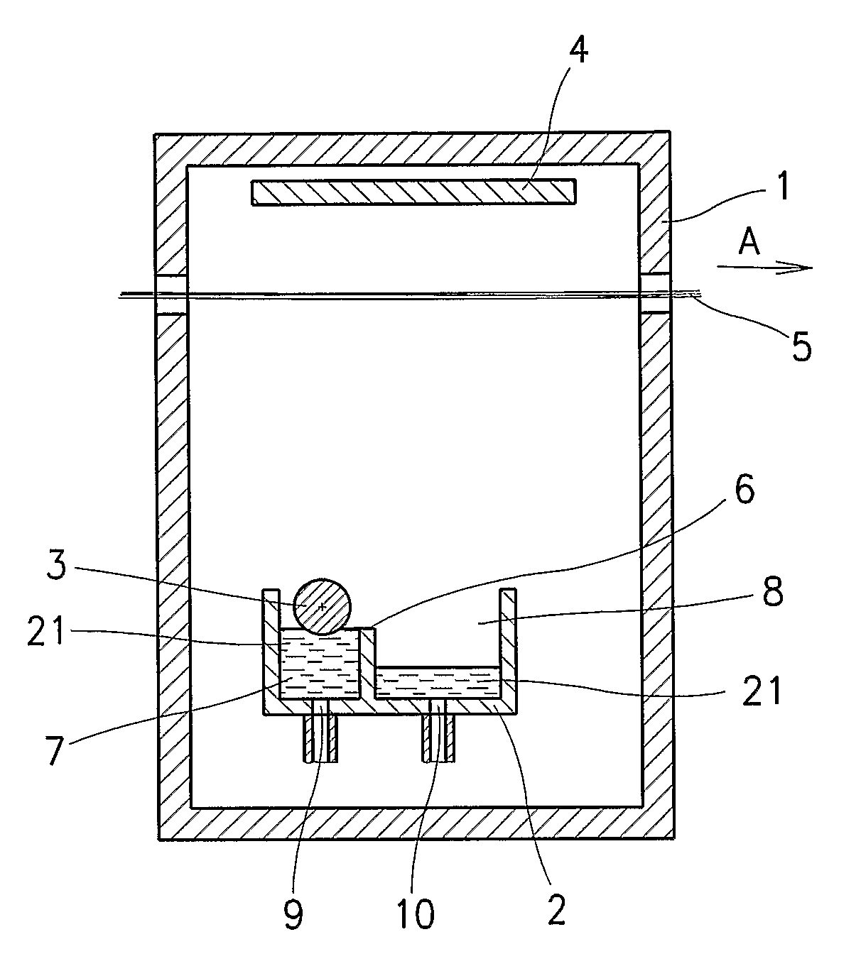
[0024]The device for production of nanofibres through electrostatic spinning of polymer solutions in electric field between at least one rotatably mounted spinning electrode of an elongated shape extending by a section of its circumference into the polymer solution in the polymer solution reservoir, and against it arranged collecting electrode according to the invention will be described in an example of embodiment represented schematically in the FIG. 1, where in the lower section of the spinning chamber 1 of the device for production of nanofibres through electrostatic spinning is arranged the reservoir 2 of polymer solution 21, in which the spinning electrode 3 of an elongated shape is mounted rotatably, which by a section of its surface extends into the polymer solution 21 contained in the reservoir 2. The spinning electrode 3 is in a known not represented manner connected with the not represented high voltage source of direct current and with not represented drive ...


PUM

PropertyMeasurementUnit
voltageaaaaaaaaaa
circumferenceaaaaaaaaaa
heightaaaaaaaaaa

Abstract

The invention relates to device for production of nanofibres through electrostatic spinning of polymer solutions comprising a spinning chamber, in which the reservoir of polymer solution is positioned, into which by a section of its circumference extends the rotating spinning electrode of elongated shape connected to one pole of high voltage source of direct current, to whose opposite pole there is connected the collecting electrode arranged in the spinning chamber against the spinning electrode, while a section of circumference of the spinning electrode extends into a polymer solution in the reservoir while the reservoir of polymer solution is divided into the inlet section, into which leads at least one inlet opening, and into which the spinning electrode extends by a section of its circumference, and the outlet section, which is provided with outlet opening.

Description

TECHNICAL FIELD[0001]Device for production of nanofibres through electrostatic spinning of polymer solutions comprising a spinning chamber, in which the reservoir of polymer solution is positioned, into which by a section of its circumference extends the rotating spinning electrode of elongated shape connected to one pole of high voltage source of direct current, to whose opposite pole there is connected the collecting electrode arranged in the spinning chamber against the spinning electrode, while a section of circumference of the spinning electrode extends into a polymer solution in the reservoir.BACKGROUND ART[0002]Known device for production of nanofibres through electrostatic spinning of polymer solutions according to the CZ 294274 comprises a spinning chamber, in which there is arranged reservoir of polymer solution with opened level. In the reservoir of polymer solution there is rotatably mounted the spinning electrode of elongated shape, e.g. in a form of cylinder, which by ...

Claims


Application Information

Patent Timeline
Patent Type & Authority Applications(United States)
IPC IPC(8): B29C47/10B29C48/285D04H1/728
CPCD01D5/0069B82Y30/00D01D5/00B82Y40/00
Inventor PETRAS, DAVIDMARES, LADISLAVCMELIK, JANFIALA, KAREL
Owner ELMARCO SRO
Why Eureka
Try Eureka