Total system for contrast delivery

a total system and contrast technology, applied in the field of total system for contrast delivery, can solve the problems of increasing costs throughout the contrast supplier chain, not universally used, and high cost of non-ionic x-ray contrast media, and achieve the effect of minimizing the chance of cross-contamination

a total system and contrast technology, applied in the field of total system for contrast delivery, can solve the problems of increasing costs throughout the contrast supplier chain, not universally used, and high cost of non-ionic x-ray contrast media, and achieve the effect of minimizing the chance of cross-contamination

US6442418B1Inactive Publication Date: 2002-08-27BAJER MEDIKAL KEHA INK

Image

  • Total system for contrast delivery
  • Total system for contrast delivery
  • Total system for contrast delivery

Examples


Embodiment Construction

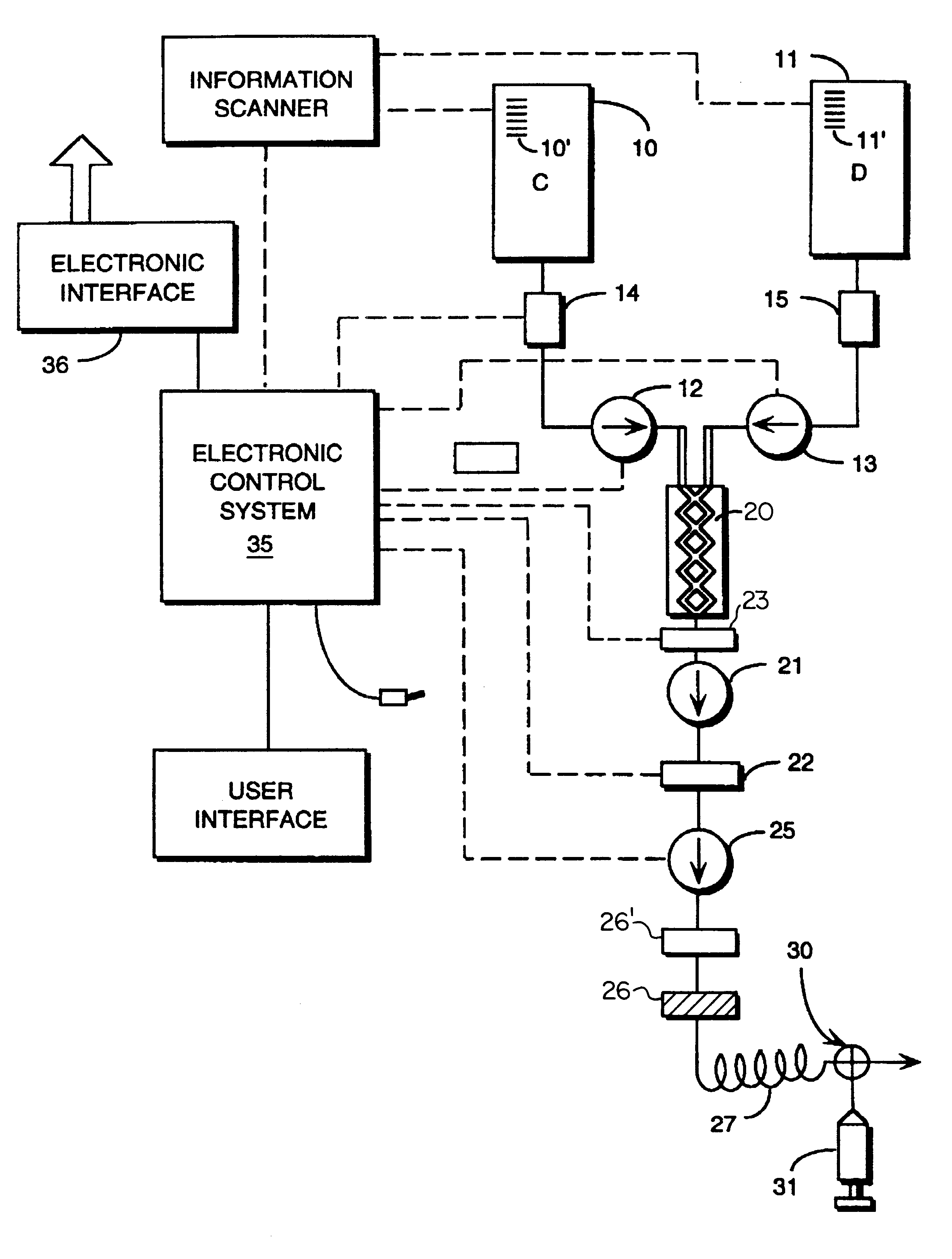
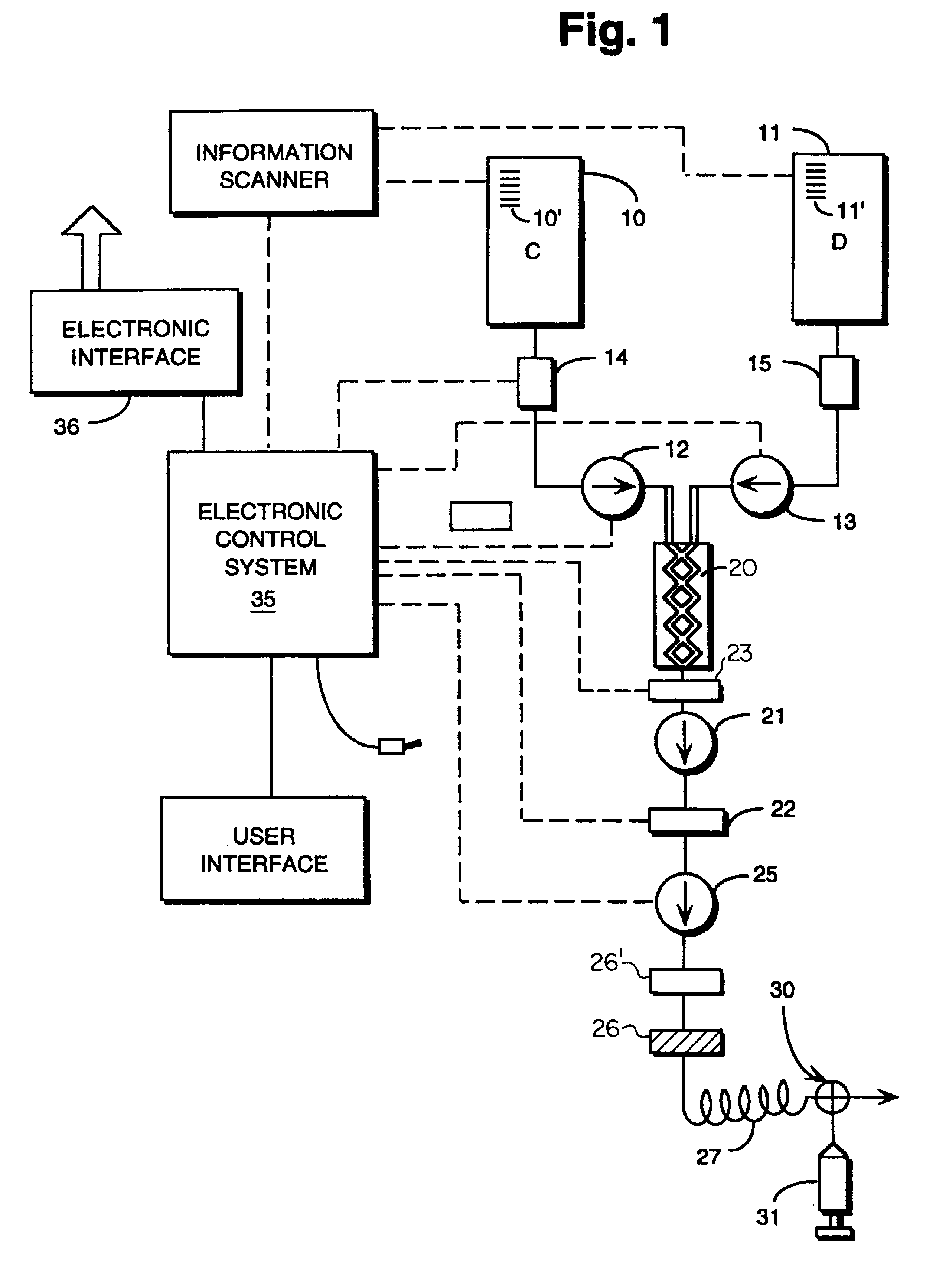
It is a goal of this invention to enable delivery of only the amount of contrast needed to a patient, with minimal contrast waste. A companion goal is to be able to deliver whatever volume of contrast is needed, when it is needed, without the arbitrary limitation of syringe or mixing chamber size. The bulk containers can hold more fluid than would be given to one patient, so its size is not a limit.

This is accomplished by changing the way contrast is packaged and delivered to the patient. Bulk contrast bottles would be manufactured and distributed to the hospital in only a few number of sizes. A given procedure room would only stock one size of bottle. The bulk contrast could only be available in a single high concentration, the highest used in current procedures, or it may be available in a limited number of different concentrations. Two bottle sizes times two concentrations is only four variations that a manufacturer would potentially have to deal with.

It is possible to eliminate ...


PUM


Abstract

A disposable unit for delivering fluid medium to one of a plurality of patients includes a sterile patient supply tube, and structure for receiving pressurized fluid medium into the patient supply tube. One or more devices is provided for precluding backflow of material from the patient to the fluid medium receiving structure, for preventing contamination of the fluid medium receiving structure and / or for preventing cross-contamination between patients.

Description

Contrast media are used in many medical diagnostic and therapeutic imaging procedures. Diagnostically these include X-ray procedures for instance, angiography, venography and urography, CT scanning, magnetic-resonance imaging [MRI], and ultrasonic imaging. Contrast media is used during therapeutic procedures such as angioplastic and other interventional radiologic procedures. Because this contrast material is injected into the patient, it must be sterile and contain a minimum of pyrogens.Presently, most contrast is provided in sterilized glass bottles, ranging in size from 20 ml to 200 ml. Plastic packages are also available. Non-ionic X-ray contrast media is expensive, on the order of $1 / ml. Ionic contrast media costs about $0.10 / ml. Non-ion contrast has fewer complications but because of the cost, it is not universally used. MRI contrast costs about $5 / ml. All the containers are single use, which means that once a bottle is opened, it should be used for that patient or thrown away...

Claims


Application Information

Patent Timeline
27 Aug 2002
Publication
US6442418B1
IPC
A61M5/168; A61M5/00
CPC
A61M5/007; A61M5/16827; A61M2205/6072; Y10S128/12; Y10S128/13
Inventors
EVANS, III, RUSSELL MORRISON; UBER, III, ARTHUR E.