
Aggressive Torque Converter Clutch Slip Control Design through Driveline Torsional Velocity Measurements

Inactive Publication Date: 2009-06-11
GM GLOBAL TECH OPERATIONS LLC
View PDF2 Cites 33 Cited by
  • Summary
  • Abstract
  • Description
  • Claims
  • Application Information

AI Technical Summary

Problems solved by technology

Because large slips between the engine output and the transmission input significantly affect the fuel economy of the vehicle, some vehicles employ a torque converter clutch (TCC) for controlling or reducing the slip between the engine and the transmission.
Thus, for those times when the TCC is locked or under low TCC controlled slip, such engine vibrations are typically passed through to the vehicle driveline.

Method used


Image

  • Aggressive Torque Converter Clutch Slip Control Design through Driveline Torsional Velocity Measurements
  • Aggressive Torque Converter Clutch Slip Control Design through Driveline Torsional Velocity Measurements
  • Aggressive Torque Converter Clutch Slip Control Design through Driveline Torsional Velocity Measurements

Examples


Embodiment Construction

[0016]The following discussion of the embodiments of the invention directed to a method for setting a minimum slip for a torque converter between a vehicle engine and transmission for various engine speeds and transmission gears is merely exemplarary in nature, and is in no way intended to limit the invention or its applications or uses.

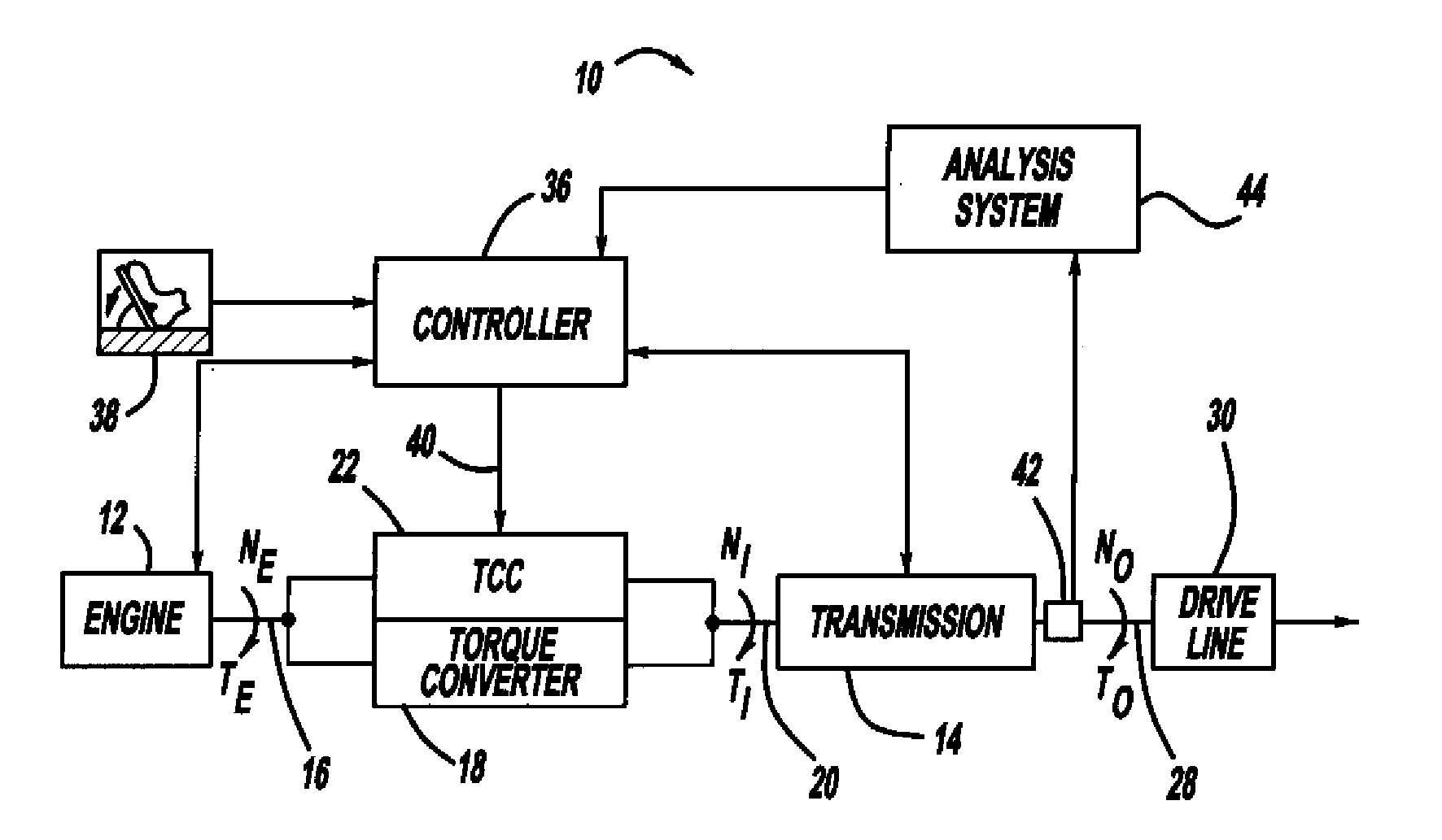
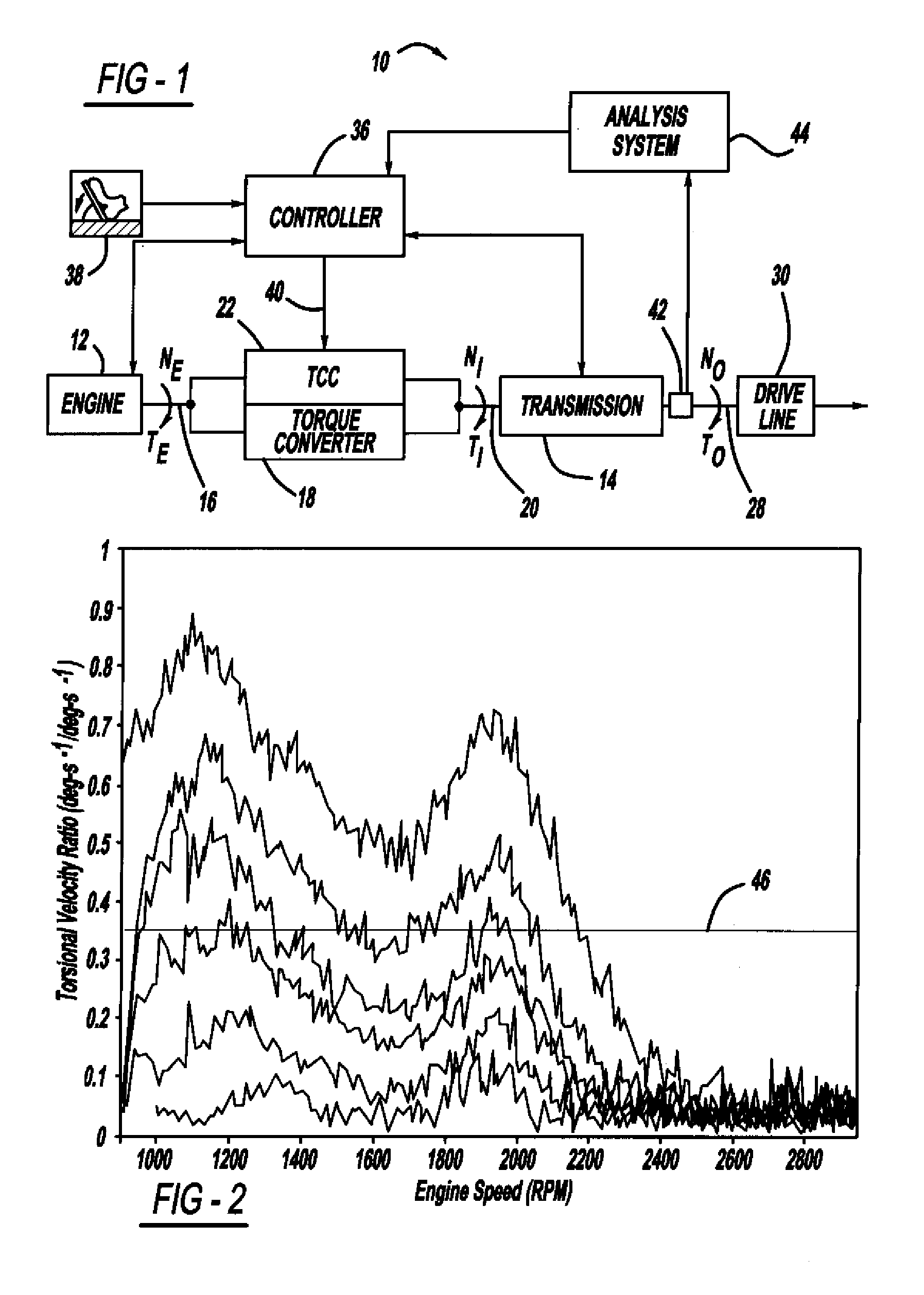
[0017]FIG. 1 is a block diagram of various powertrain components of a vehicle 10. The powertrain components include an engine 12 and a transmission 14. An output shaft of the engine 12, represented by line 16, is coupled to one end of a torque converter 18, and an input shaft of the transmission 16, represented by line 20, is coupled to an opposite end of the torque converter 18. As discussed above, the torque converter 18 transfers rotational energy from the engine 12 to the transmission 14 using hydraulic fluid so that the engine 12 can be disengaged from the transmission 14 when necessary. A TCC 22 sets a torque converter slip in the torque conver...


PUM


Abstract

A system and method for setting the slip of a torque converter for a plurality of selected engine speeds and transmission gears. The method includes populating a table off-line, typically using a dynamometer, with torque converter slips for a plurality of selected engine speeds and transmission gears. A speed sensor is used to measure vibrations transmitted through the torque converter to the driveline of the vehicle. The sensor signal is sent to an analyzing system where it is converted to the frequency domain. A separate minimum slip value for each selected engine speed and transmission gear is stored in a table so that during vehicle operation, a controller will instruct the torque converter clutch to set the desired converter slip for the current engine speed and transmission gear provided for a particular throttle position and / or engine torque.

Description

CROSS-REFERENCE TO RELATED APPLICATIONS[0001]This application claims priority to U.S. Provisional Patent Application Ser. No. 61 / 012,194, filed Dec. 7, 2007, titled “Aggressive Torque Converter Clutch Slip Control Design through Driveline Torsional Velocity Measurements.”BACKGROUND OF THE INVENTION[0002]1. Field of the Invention[0003]This invention relates generally to a system and method for setting the slip in a torque converter of a vehicle and, more particularly, to a system and method for populating a table of minimum torque converter slips for various engine speeds and transmission gears off-line, and then storing the table on the vehicle for later use, so as to minimize vehicle driveline vibrations and provide good fuel economy.[0004]2. Discussion of the Related Art[0005]Internal combustion engine vehicles that employ automatic transmissions typically include a torque converter positioned between the engine and the transmission of the vehicle. A torque converter is a fluid co...

Claims


Application Information

Patent Timeline
IPC IPC(8): B60W10/02G01M13/02G06F19/00
CPCG01M13/022Y10T477/6333Y10T477/755
Inventor OTANEZ, PAUL G.SAMIE, FARZADLEE, CHUNHAO J.
Owner GM GLOBAL TECH OPERATIONS LLC
Features
  • Generate Ideas
  • Intellectual Property
  • Life Sciences
  • Materials
  • Tech Scout
  • Unparalleled Data Quality
  • Higher Quality Content
  • 60% Fewer Hallucinations
Learn More