Chemical liquid infusion system

a liquid injection system and liquid injection technology, applied in the field of chemical solution injection system, can solve the problems of cumbersome operation, difficult to place the rfid chip on such a cylinder flange, and more difficult to place the air coil, so as to achieve favorable wireless communication and improve the communication performance of the rfid chip.

Inactive Publication Date: 2009-06-11
NEMOTO KYORINDO KK
View PDF7 Cites 75 Cited by
  • Summary
  • Abstract
  • Description
  • Claims
  • Application Information

AI Technical Summary

Benefits of technology

[0024]In the chemical solution injection system of the present invention, the RFID chip having the predetermined elongated shape is wound on the outer circumference surface of the cylinder member of the chemical solution syringe, and the amplification antenna having the shape encircling the outer circumference surface of the cylinder me

Problems solved by technology

This entering operation is cumbersome.
It is extremely difficult to place the RFID chip on such a cylinder flange, and it is more difficult to place the air coils there.
It is difficult to dispose such a chip antenna on the cylinder flange of the chemical solution syringe.
It is contemplated that the RFID chip and the air coils are placed within the cylinder flange to prevent such breaks, but that arrangement significantly reduces the productivity of the chemical solution syringe and thus is not a practical idea.
It has been revealed, however, that the abovementioned RFID chip did not provide sufficient output in wireless communication and could not achieve favorable wireless communication, unless an RFID reader is placed close thereto.
Particularly, since the abovem

Method used


Image

  • Chemical liquid infusion system
  • Chemical liquid infusion system
  • Chemical liquid infusion system

Examples


embodiment

Configuration of Embodiment

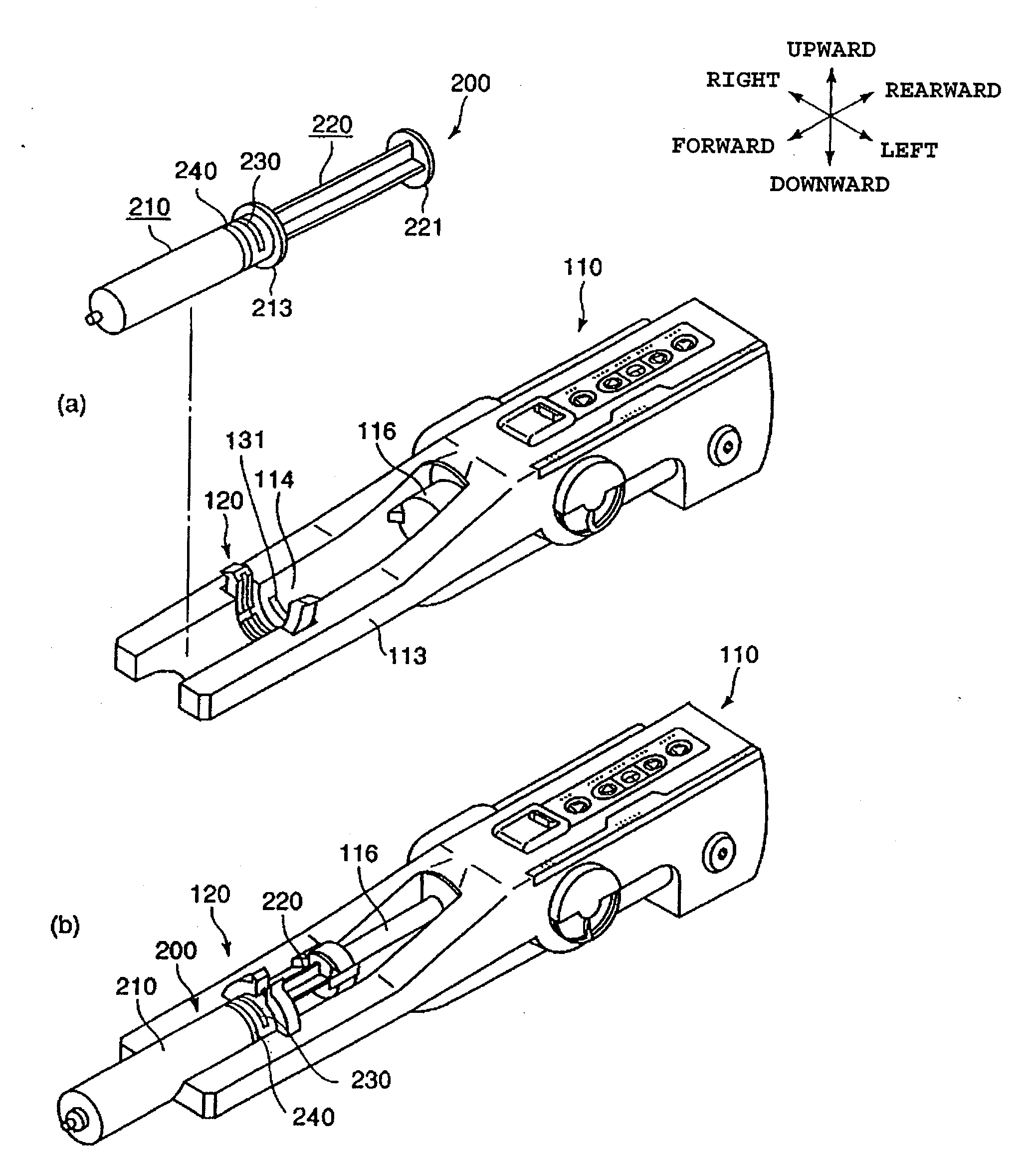
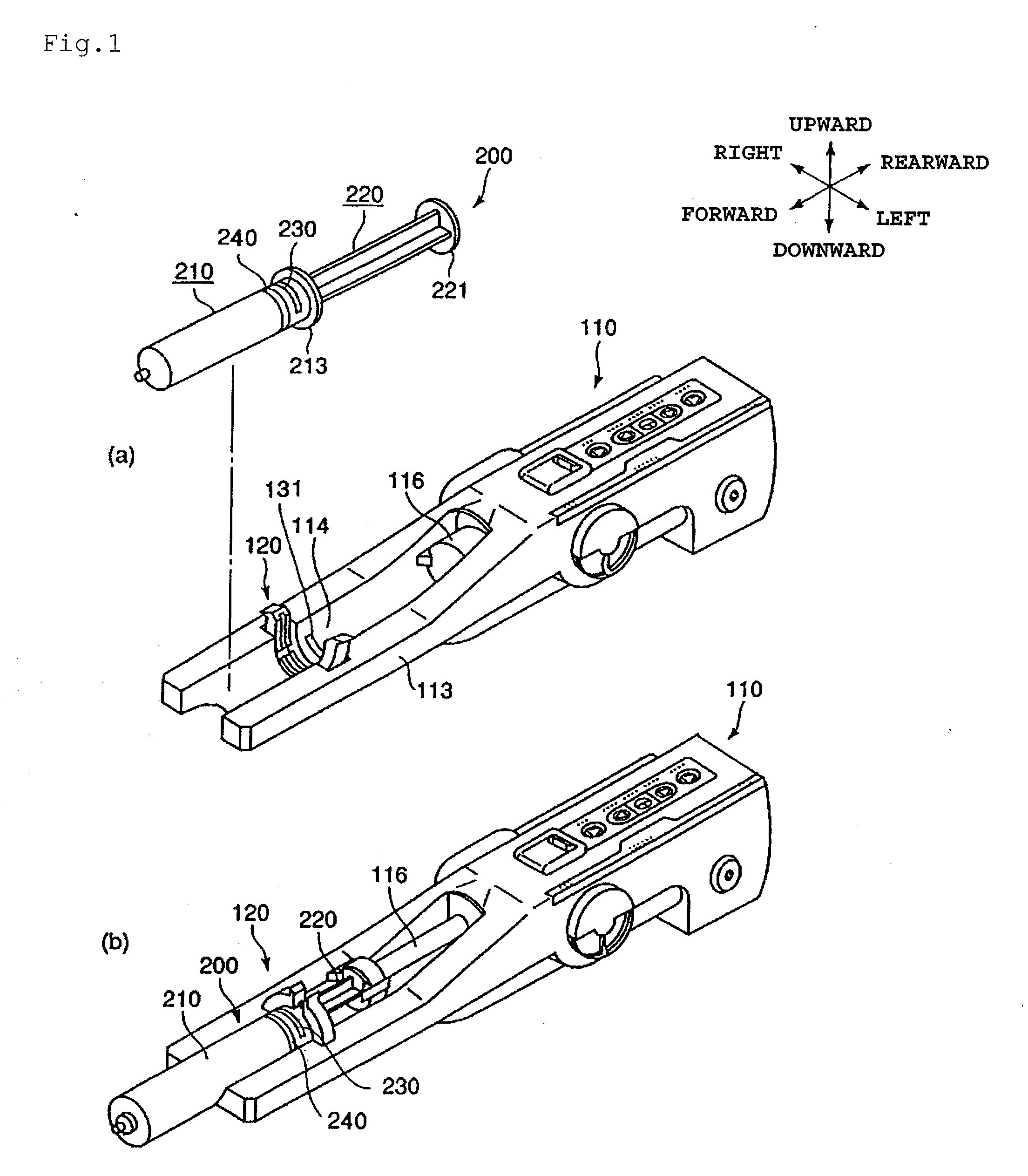
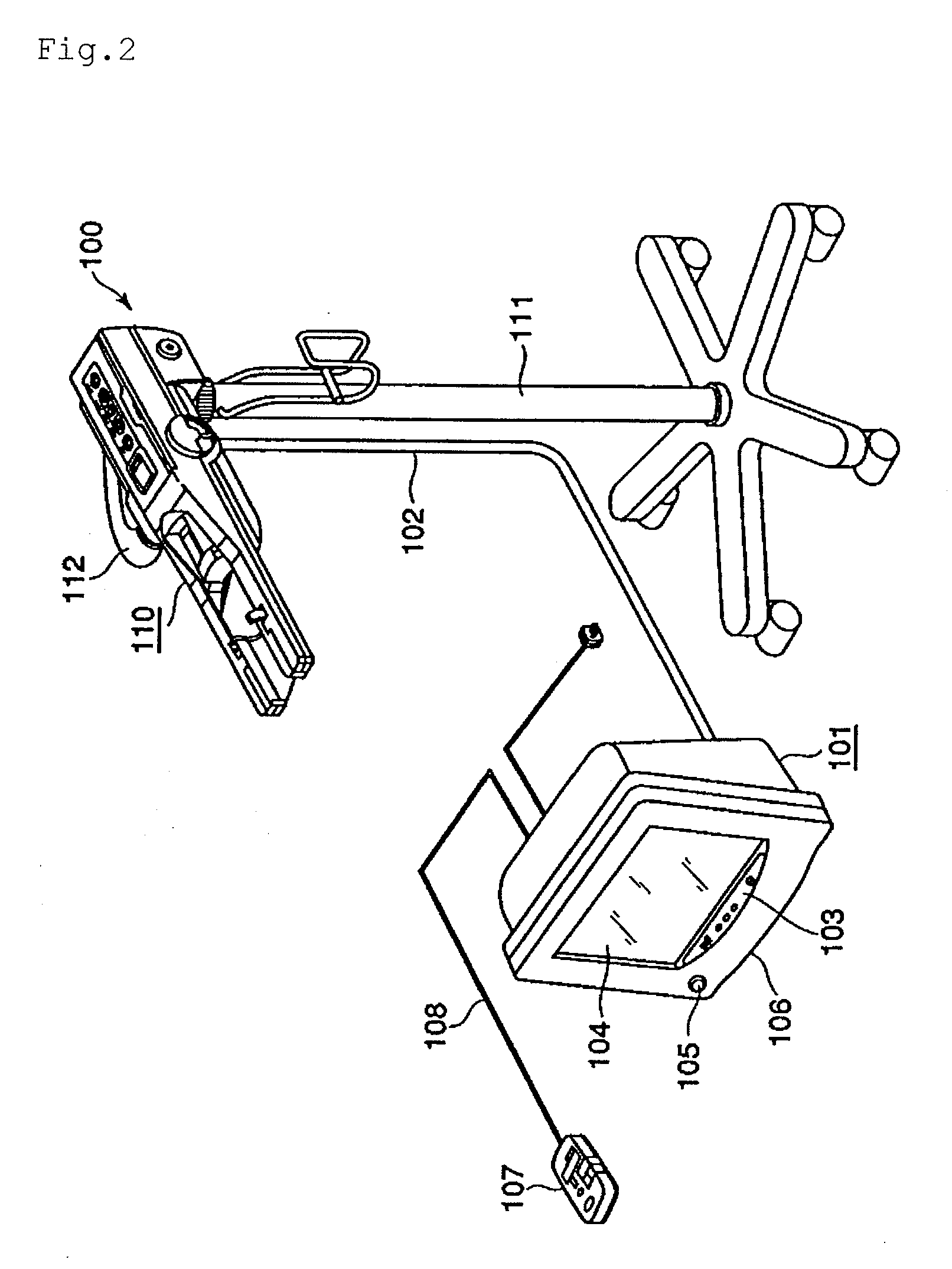
[0058]An embodiment of the present invention will hereinafter be described with reference to FIGS. 1 to 11. As shown in FIGS. 1 to 4, chemical solution injection system 1000 of the embodiment according to the present invention comprises chemical solution injector 100, chemical solution syringe 200, and CT scanner 300 which is an imaging diagnostic apparatus. The system is provided for taking diagnostic images of a patient (not shown) injected with a chemical solution such as a contrast medium, described later in detail.

[0059]As shown in FIGS. 3 and 4, CT scanner 300 includes imaging diagnostic unit 301 and imaging control unit 302. The imaging diagnostic unit 301 and imaging control unit 302 are wire-connected each other through communication network 303. Imaging diagnostic unit 301 shoots a diagnostic image of a patient. Imaging control unit 302 controls the operation of imaging diagnostic unit 301.

[0060]As shown in FIGS. 1 and 5, chemical solution syring...


PUM


Abstract

A chemical solution injection system, wherein a RFID chip (230) is mounted on a chemical liquid syringe (200) in the state of being wrapped around the outer surface of the cylinder member (210) thereof. An amplification antenna (240) wrapped one turn around the outer surface of the cylinder member (210) is disposed at the front of the RFID chip (230) parallel with each other. Since the communication performance of the RFID chip is increased by the amplifying antenna, the RFID chip (230) of the chemical solution syringe (200) is allowed to satisfactorily communicate with the RFID reader (131) of injection head (110).

Description

TECHNICAL FIELD[0001]The present invention relates to a chemical solution injection system for injecting a chemical solution of chemical solution syringe into a patient by using a chemical solution injector, and more particularly, to a chemical solution injection system for injecting a contrast medium into a patient whose diagnostic images are taken by an imaging diagnostic apparatus such as a CT (Computed Tomography) scanners.BACKGROUND ART[0002]Presently available imaging diagnostic apparatuses for capturing diagnostic images of patients include CT scanners, MRI (Magnetic Resonance Imaging) apparatuses, PET (Positron Emission Tomography) apparatuses, ultrasonic diagnostic apparatuses, CT angiography apparatuses, MRA (MR angiography) apparatuses and the like. When the abovementioned imaging diagnostic apparatuses are used, a chemical solution such as a contrast medium and physiological saline may be injected into a patient. Chemical solution injectors for automatically performing t...

Claims


Application Information

Patent Timeline
IPC IPC(8): A61M5/145
CPCA61M5/007A61M5/14546A61M5/1456A61M2205/6054A61M2205/3569A61M2205/3592A61M2205/60A61M5/172
Inventor NEMOTO, SHIGERUONO, SEIICHISAKAKIBARA, MASAHIRO
Owner NEMOTO KYORINDO KK
Why Eureka
Try Eureka