Method, system and apparatus for an efficient design and operation of a pump motor

a pump motor and efficient technology, applied in the direction of machines/engines, liquid transfer devices, positive displacement liquid engines, etc., can solve the problems of high suction force in the 2′′ pool system, inefficient conventional pool design, related drowning deaths,

Inactive Publication Date: 2009-06-18
GORMAN JOHN +2
View PDF0 Cites 70 Cited by
  • Summary
  • Abstract
  • Description
  • Claims
  • Application Information

AI Technical Summary

Problems solved by technology

Conventional pool designs can be characterized as inefficient due to a combination of inefficient hydraulic designs that require a high-power pump to move water through the system at high speed and at high pressure.
Each year there are pool related drowning fatalities resulting from the high pressures and high suction forces found in 2″ diameter pools when hair, clothing, or body parts are sucked into the 2″ diameter pools hydraulic system water inlets.
The high suction force in a 2″ pool system is the results from the high water pressure and high water velocity required to move sufficient volumes of water to keep a pool hygienically clean.
In the past designs for an efficient pool motor is exemplified by timing the operation of a two-speed motor and does not provide a solution that can increase the efficiency of a single speed pump.
It does not address improved hydraulics, multiple pump priming, or a method of improving the efficiency of single speed motors that are common in conventional pool designs.

Method used


Image

  • Method, system and apparatus for an efficient design and operation of a pump motor
  • Method, system and apparatus for an efficient design and operation of a pump motor
  • Method, system and apparatus for an efficient design and operation of a pump motor

Examples


Embodiment Construction

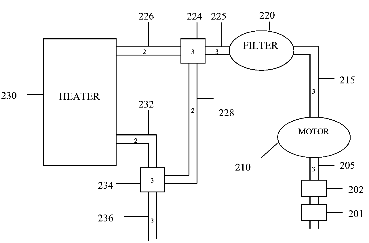
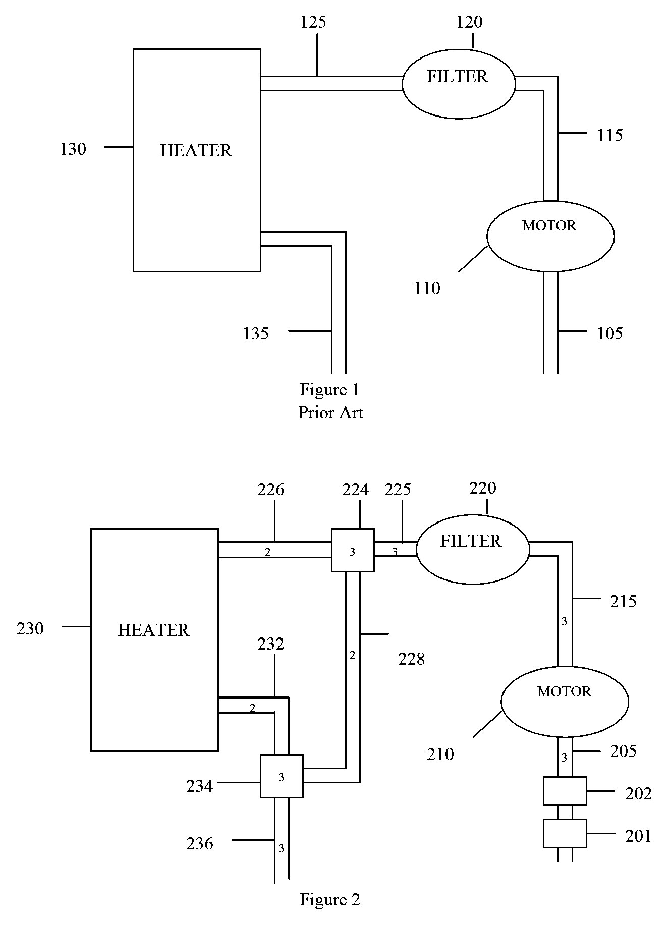
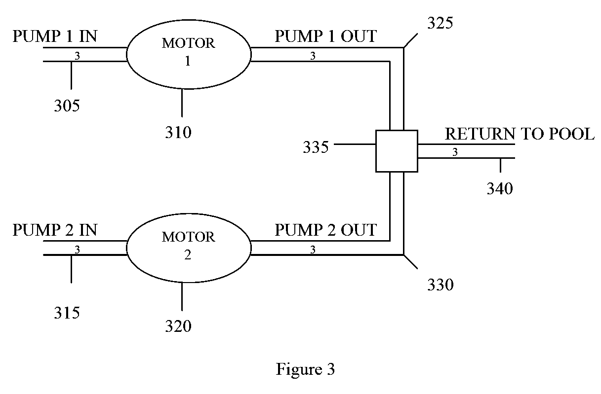
[0030]The present invention is best understood by reference to the detailed figures and description set forth herein.

[0031]Embodiments of the invention are discussed below with reference to the Figures. However, those skilled in the art will readily appreciate that the detailed description given herein with respect to these figures is for explanatory purposes as the invention extends beyond these limited embodiments. For example, it should be appreciated that those skilled in the art will, in light of the teachings of the present invention, recognize a multiplicity of alternate and suitable approaches, depending upon the needs of the particular application, to implement the functionality of any given detail described herein, beyond the particular implementation choices in the following embodiments described and shown. That is, there are numerous modifications and variations of the invention that are too numerous to be listed but that all fit within the scope of the invention. Also, ...


PUM


Abstract

A method of operating a controller for a pool pump motor includes the steps of setting an operating mode for the pool pump motor, setting a torque value for the pool pump motor corresponding to the operating mode, setting a high operating threshold and a low operating threshold corresponding to the torque value, operating the pool pump motor in a constant torque mode using the torque value, monitoring an operating parameter of the pool pump motor corresponding to a load on the pool pump motor, discontinuing operating the pool pump motor when the operating parameter is higher than the high operating threshold or lower than the low operating threshold and signaling a pool pump motor fault upon the discontinuing operating the pool pump motor. The operating parameter of the pool pump motor is RPM or current supplied to the pool pump motor. Additionally disclosed are energy efficient pool hydraulic design techniques that increase the energy efficiency of hydraulic systems.

Description

CROSS-REFERENCE TO RELATED APPLICATIONS[0001]The present Utility patent application claims priority benefit of the U.S. provisional application for patent Ser. No. 61 / 013,280 filed on Dec. 12, 2007 under 35 U.S.C. 119(e). The contents of this related provisional application are incorporated herein by reference for all purposes.FEDERALLY SPONSORED RESEARCH OR DEVELOPMENT[0002]Not applicable.REFERENCE TO SEQUENCE LISTING, A TABLE, OR A COMPUTER LISTING APPENDIX[0003]Not applicable.COPYRIGHT NOTICE[0004]A portion of the disclosure of this patent document contains material that is subject to copyright protection. The copyright owner has no objection to the facsimile reproduction by anyone of the patent document or patent disclosure as it appears in the Patent and Trademark Office, patent file or records, but otherwise reserves all copyright rights whatsoever.FIELD OF THE INVENTION[0005]The present invention relates generally to an efficient pool design. More particularly, the invention ...

Claims


Application Information

Patent Timeline
Patent Type & Authority Applications(United States)
IPC IPC(8): G05D7/06H02P7/00
CPCF04D15/0066F04D13/14Y10T137/85954Y10T137/85986Y10T137/86027Y10T137/86131
Inventor GORMAN, JOHNLIZALDE, WILLIAMKULAKOWSKI, ROBERT
Owner GORMAN JOHN
Why Eureka
Try Eureka