Low cost high conductance chamber

a high conductance chamber, low cost technology, applied in the direction of cable/conductor manufacturing, coatings, chemical vapor deposition coatings, etc., can solve the problems of limited pressure gradients within the process cavity, and inability to provide uniform and efficient pumping of process gases. achieve the effect of high conductance, small processing cavity size, and improved gas flow uniformity

Inactive Publication Date: 2009-06-18
INTEVAC
View PDF8 Cites 3 Cited by
  • Summary
  • Abstract
  • Description
  • Claims
  • Application Information

AI Technical Summary

Benefits of technology

[0009]Aspects of the present invention provide a process chamber where an undercut is formed to enlarge a pumping area below the processing cavity to produce a chamber with high conductance, while maintaining the size of the processing cavity itself small.
[0010]Aspects of the present invention provide a process chamber that improves uniformity of gas flow to a vacuum pump.

Problems solved by technology

One problem typically encountered in conventional processing chambers is that the exhaust systems typically do not provide uniform and efficient pumping of the process gases from the processing chamber.
In conventional processing chambers, the uniformity of process gas flow and the efficiency of process gas exhaust are limited by a variety of factors, such as the interior volume of the chamber, the placement of the chuck in the chamber, the size of the exhaust outlet, and the position of the exhaust outlet.
These factors cause restrictions in the gas flow path, leading to pressure gradients within the process cavity.
With the hole in the bottom, the substrate support member often obstructs the flow of exhaust gases or otherwise results in non-uniform exhausting of the process chamber.
This non-uniform exhausting of gases may lead to non-uniform processing results.
The size of the exhaust outlet may limit conductance from the chamber to the exhaust system.
Further, the abrupt transition between the exhaust outlet and the chamber wall disrupts smooth flow of the process gases to the exhaust outlet and hinders the exhaust process.

Method used


Image

  • Low cost high conductance chamber
  • Low cost high conductance chamber
  • Low cost high conductance chamber

Examples


Embodiment Construction

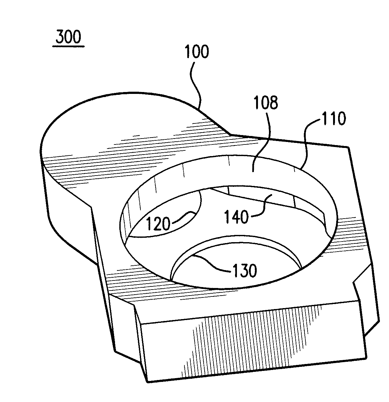
[0030]FIGS. 1, 2, 3A and 3B show perspective views of a chamber during stages of manufacturing or fabrication according to the aspects of the invention. A process chamber or a processing chamber used for processing substrates including semiconductor wafers may be referred to simply as a chamber.

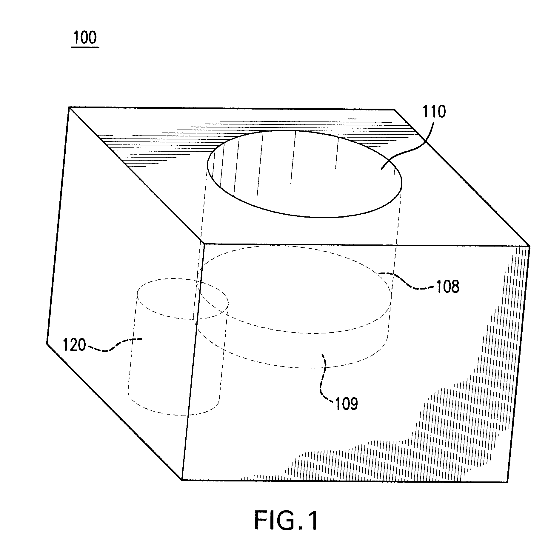
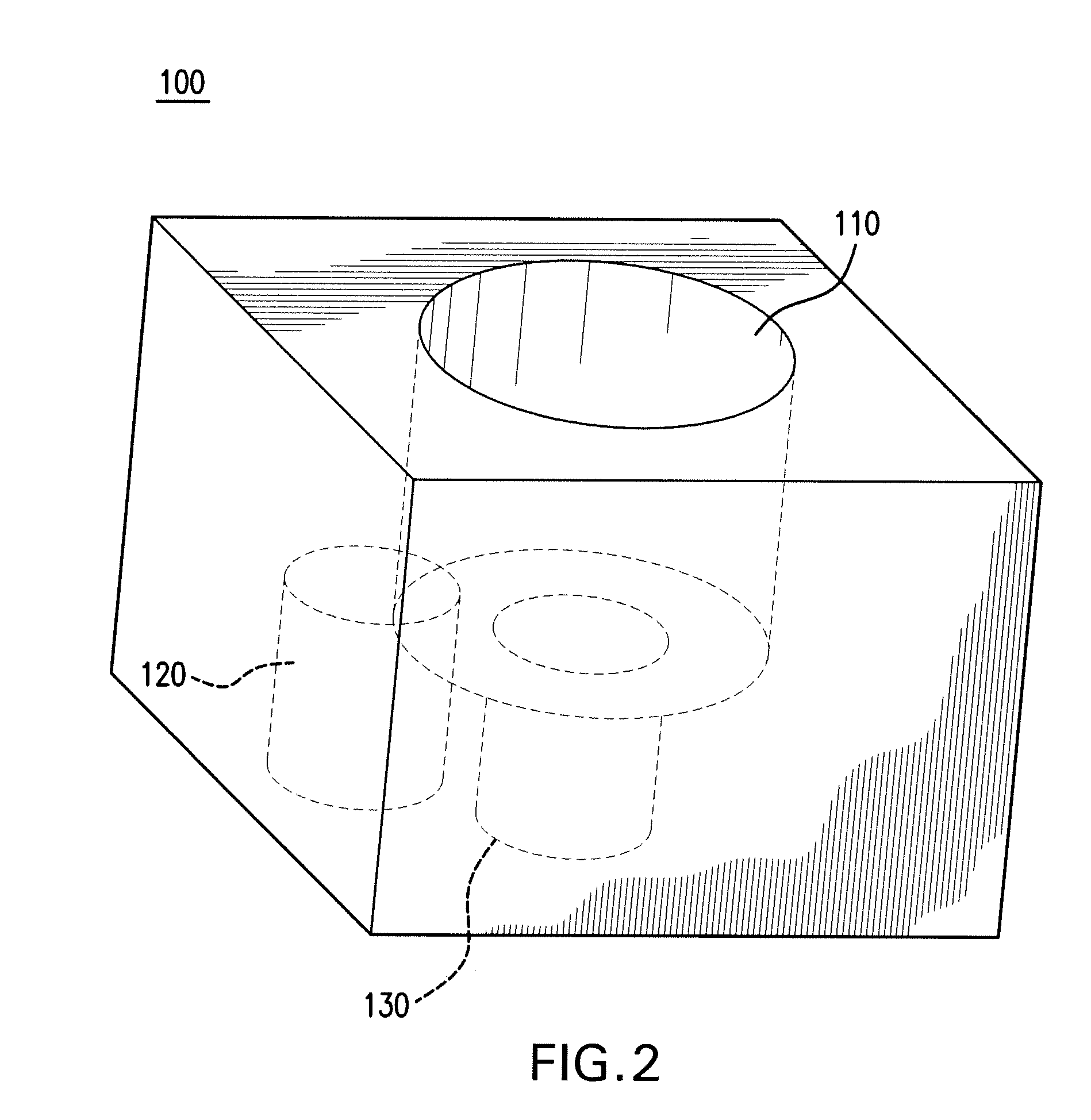
[0031]FIG. 1 shows a piece or a block of material 100. A process cavity 110 is formed in one part of the block 100. A pump cavity 120 is formed in another part of the block 100. The process cavity 110 and the pump cavity 120 are both cylindrical. The process cavity forms a cylinder or a cylindrical volume open to one surface of the block 100 and the pump cavity 120 forms another cylindrical volume open at an opposite surface of the block 100.

[0032]The piece of material 100 may be formed from a metal such as aluminum. The piece of material 100 may come in any prefabricated geometrical form. The piece of material 100 may be cubic.

[0033]When the piece of material 100 is cubic, the process cavity...


PUM

PropertyMeasurementUnit
diameteraaaaaaaaaa
diameteraaaaaaaaaa
gas pressureaaaaaaaaaa

Abstract

A process chamber having high conductance and a method of manufacturing the process chamber are disclosed. The process chamber is machined from a single piece of aluminum where a process cavity and a pump cavity are created by intersecting cylinders. A substrate opening is also created at a bottom of the process cavity to provide conduit for services, such as cooling gas and electrical connections. A large undercut area is formed at a top of the pump cavity between the pump cavity and the process cavity. The undercut extends past the process chamber centerline at the process cavity. A circular saw is used to remove material and create a plenum which extends beyond the process cavity centerline.

Description

BACKGROUND[0001]1. Field of the Invention[0002]This invention generally relates to substrate processing chambers and more particularly to design and manufacture of substrate processing chambers that include vacuum pumping.[0003]2. Related Arts[0004]A variety of processes may be performed on a semiconductor substrate that include etch, chemical vapor deposition, physical vapor deposition, and other plasma or non-plasma processes. Many of these processes require a continuous exhaust of gases in the chamber to be replaced by new process gases. A relative vacuum is usually established and maintained in the chamber. Vacuum processing chambers are typically designed to meet performance specifications which include the degree of vacuum required within the chamber.[0005]One problem typically encountered in conventional processing chambers is that the exhaust systems typically do not provide uniform and efficient pumping of the process gases from the processing chamber. In conventional proce...

Claims


Application Information

Patent Timeline
Patent Type & Authority Applications(United States)
IPC IPC(8): H01B13/00B23P17/04C23C16/54
CPCH01L21/67017Y10T29/49H01L21/6719H01L21/00H01L21/02
Inventor SAMIR, TUGRULBARNES, MICHAEL S.BLUCK, TERRY
Owner INTEVAC
Why Eureka
Try Eureka