Casing structure and electronic device

Inactive Publication Date: 2009-06-18
FUJITSU LTD
View PDF10 Cites 0 Cited by
  • Summary
  • Abstract
  • Description
  • Claims
  • Application Information

AI Technical Summary

Benefits of technology

[0050]4. It is possible to permit maximum inhibition of increase in size compared to

Problems solved by technology

Accordingly, it becomes difficult to apply the casing structure to LCD-integrated personal computers to which increased load is expected to be applied.
These problems may generally exist in

Method used


Image

  • Casing structure and electronic device
  • Casing structure and electronic device
  • Casing structure and electronic device

Examples


Embodiment Construction

[0060]Embodiments of a casing structure and an electronic device having the casing structure will be described more specifically with reference to accompanying drawings.

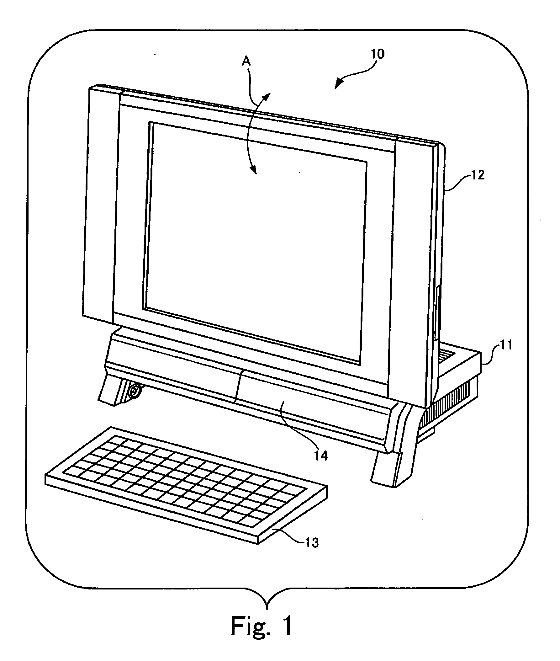
[0061]FIG. 1 is a perspective view illustrating an LCD-integrated personal computer that is an embodiment of an electronic device according to the present invention.

[0062]Referring to FIG. 1, the LCD-integrated personal computer 10 includes a main body section 11 having a CPU (Central Processing Unit), a memory, and a hard disk; a liquid crystal display 12 connected to the main body section 11 to be rotatable with a hinge in the direction of an arrow A shown in FIG. 1; and a keyboard 13 for entering a user's indication or text information to the LCD-integrated personal computer 10. The keyboard 13 may be a wireless keyboard that wirelessly transmits information entered by a user to the main body section 11. The hinge will be described later. In this embodiment, the keyboard 13 enters a receiving space provided under ...


PUM


Abstract

The casing structure includes a first frame having a top surface section; a second frame having a top surface section and a bent section that is bent on the top surface section at a location where the the second frame abuts the first frame; and a hinge mounted over the top surface section of the first frame including the location and the top surface section of the second part. The hinge secures an LCD to the second frame.

Description

BACKGROUND OF THE INVENTION[0001]1. Field of the Invention[0002]The present invention relates to a casing structure for an electronic device, such as a personal computer, and an electronic device having the casing structure as a frame.[0003]2. Description of Related Art[0004]In recent years, a display-integrated personal computer gains popularity among desktop personal computers in which a display has been integrated with a main body of the computer.[0005]FIG. 8 is a perspective view of an exemplary display-integrated personal computer.[0006]A liquid crystal display (LCD) integrated personal computer 20 that has a liquid crystal display 22 is shown in FIG. 8, as an example of such a display-integrated personal computer. The LCD-integrated personal computer 20 includes a main body section 21 having a CPU (Central Processing Unit), a memory, and a hard disk; the LCD 22 connected to the main body section 21 to be rotatable with a hinge in the direction of an arrow D shown in FIG. 8; an...

Claims


Application Information

Patent Timeline
IPC IPC(8): G06F1/16
CPCG06F1/181G06F1/1601G06F1/16G06F2200/1631
Inventor ISHIKAWA, MASAKIMIYAKOSHI, NAOKI
Owner FUJITSU LTD
Why Eureka
Try Eureka