Device for decoupling a bearing bracket

a bearing bracket and device technology, applied in the direction of couplings, bearing unit rigid supports, liquid fuel engines, etc., can solve the problems of difficult design of stress-limiting screws, uncontrolled breakage of stress-limiting screws, etc., to eliminate shear forces and improve the control of the decoupling function

Inactive Publication Date: 2009-06-18
SN DETUDE & DE CONSTR DE MOTEURS DAVIATION S N E C M A
View PDF17 Cites 6 Cited by
  • Summary
  • Abstract
  • Description
  • Claims
  • Application Information

AI Technical Summary

Benefits of technology

[0010]One object of the present invention is to improve the control over the decoupling function. This object is achieved by eliminating the shear forces that may arise in a stress-limiting screw of a device for decoupling a bearing bracket. Thus, the stress-limiting screws become sensitive only to the tensile forces for which they were designed.

Problems solved by technology

When imbalance appears, the upstream part and the downstream part shift relative to one another in a circular relative movement which has the effect of subjecting the stress-limiting screw to shear forces, because of the tangential contact around the stress-limiting screw, and this may lead to uncontrolled breakage of the stress-limiting screws.
It is also difficult to design a stress-limiting screw that is capable of accounting both for tensile forces and shear forces.

Method used


Image

  • Device for decoupling a bearing bracket
  • Device for decoupling a bearing bracket
  • Device for decoupling a bearing bracket

Examples


Embodiment Construction

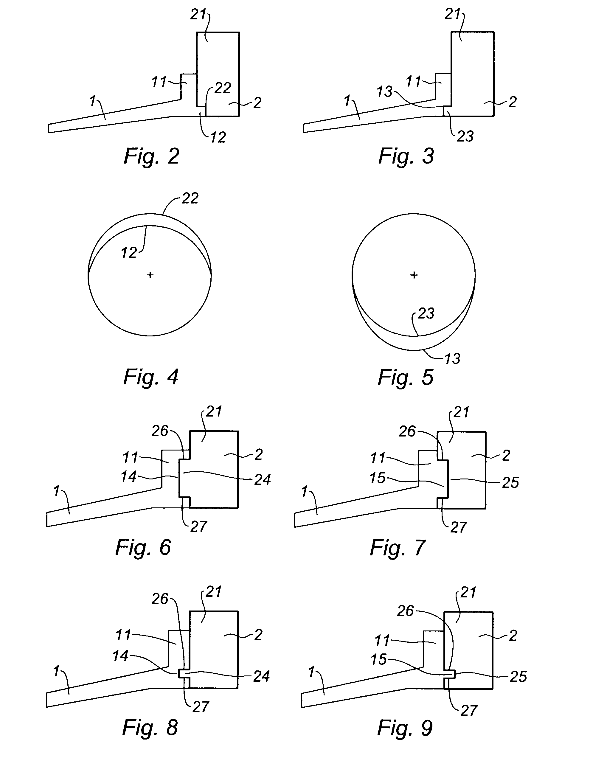
[0028]In order to lessen, or even eliminate, the shear forces on the stress-limiting screws 3, a first part of the solution proposed by the invention is to replace the external 12 and 22 or internal 13 and 23 centering means, which are single centering means, with a means known as a “dual centering” means.

[0029]The dual centering means, 14 and 24 or 15 and 25, consists of a circular groove 14 or 25 and a circular rib 15 or 24 of complementing shape. The circular groove 14 or 25 and the circular rib 15 or 24 are in contact via their flanks 26 and 27 that offer two parallel contact surfaces. “Dual centering” thus provides centering by means of these two parallel surfaces whereas a single centering means like the one depicted in FIGS. 2 and 3 offers just one contact surface for centering.

[0030]According to a first embodiment of the invention which is depicted in FIG. 6, the circular groove 14 is located on the upstream part 1 and the circular rib 24 is located on the downstream part 2....


PUM


Abstract

The invention relates to a device for decoupling a bearing bracket in a turbomachine, said bearing bracket having an upstream part and a downstream part respectively comprising a plurality of upstream holes and downstream holes through which stress-limiting screws pass, which device comprises, between each upstream hole and the stress-limiting screw that passes through it, a clearance that prevents any contact between the upstream hole and the stress-limiting screw, and is a device wherein the upstream part and the downstream part of the bearing bracket are in mutual contact via surfaces that form a dual centering means.

Description

BACKGROUND OF THE INVENTION[0001]The present invention relates to a device for decoupling the bracket of a bearing of a rotating shaft in a turbomachine. A bearing bracket such as this is liable to break its connection with the turbomachine stator upon the onset of imbalance in order to avoid damage to the turbomachine.[0002]A turbomachine comprises, for upstream to downstream in the direction in which the gases flow, a compressor, a combustion chamber and a turbine. The purpose of the compressor is to raise the pressure of the air supply to the combustion chamber. The purpose of the turbine is to drive the rotation of the compressor by tapping off some of the pressure energy of the hot gases leaving the combustion chamber and converting it into mechanical energy.[0003]The compressor and the turbine are made of a first set of fixed parts that make up the stator and of a second set of parts capable of being rotated relative to the stator and which make up the rotor.[0004]The compress...

Claims


Application Information

Patent Timeline
Patent Type & Authority Applications(United States)
IPC IPC(8): F16C35/06F01D25/16
CPCF01D21/045F05D2230/64F16D9/06F05B2260/3011
Inventor DECERLE, ERIC NICOLASDUCHATELLE, THIERRY FRANCOIS MAURLCEMOLINARI, OLIVIER MICHAELSANCHEZ, ARNAUD
Owner SN DETUDE & DE CONSTR DE MOTEURS DAVIATION S N E C M A
Why Eureka
Try Eureka