Wind blade joint bonding grid

a wind blade and joint technology, applied in wind turbine blades with parallel air flow, wind energy generation, liquid fuel engine components, etc., can solve the problems of undesirable weight of wind turbine blades, large wind turbine blades, and inconvenient fabrication, so as to reduce cost, facilitate assembly on-site, and strong and uniform junctions

Active Publication Date: 2009-06-18
GENERAL ELECTRIC CO
View PDF8 Cites 125 Cited by
  • Summary
  • Abstract
  • Description
  • Claims
  • Application Information

AI Technical Summary

Benefits of technology

[0010]One advantage of an embodiment is that the bonding grid provides controlled temperature and distribution of adhesive, and provides a quality control to validate the filling of the cavity.
[0011]Another advantage is that the bonding grid provides a means of controlling the space between joined components to provide strong and uniform junctions between segments.
[0012]Still another advantage is that

Problems solved by technology

Wind turbine blades may be very large and may require fabrication in two or more pieces.
The components may be joined together by adhesive or interlocking structure, but conventional joining techniques fail to provide sufficient bonding strength or sufficient durability between sections during wind turbine operat

Method used


Image

  • Wind blade joint bonding grid
  • Wind blade joint bonding grid
  • Wind blade joint bonding grid

Examples


Embodiment Construction

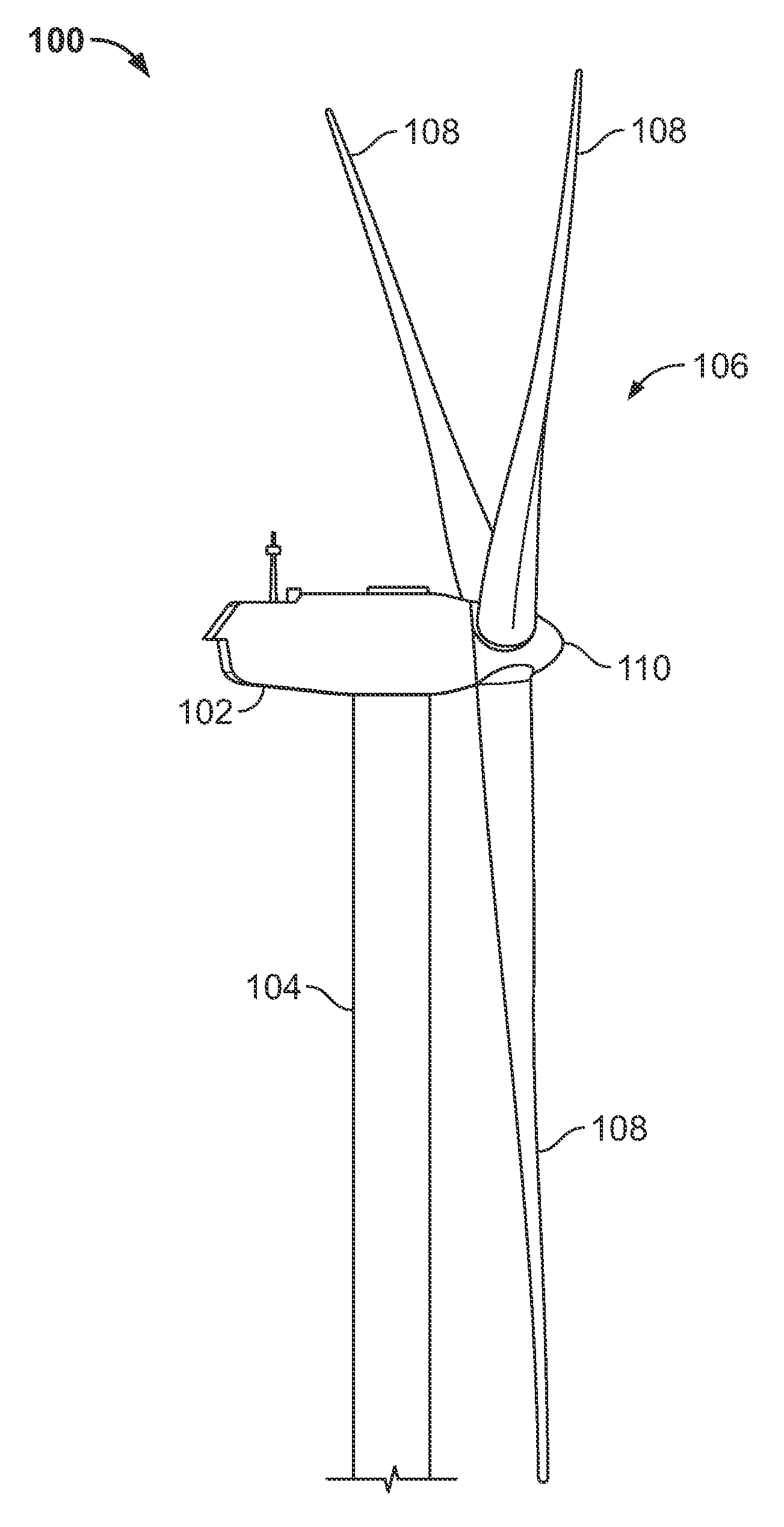
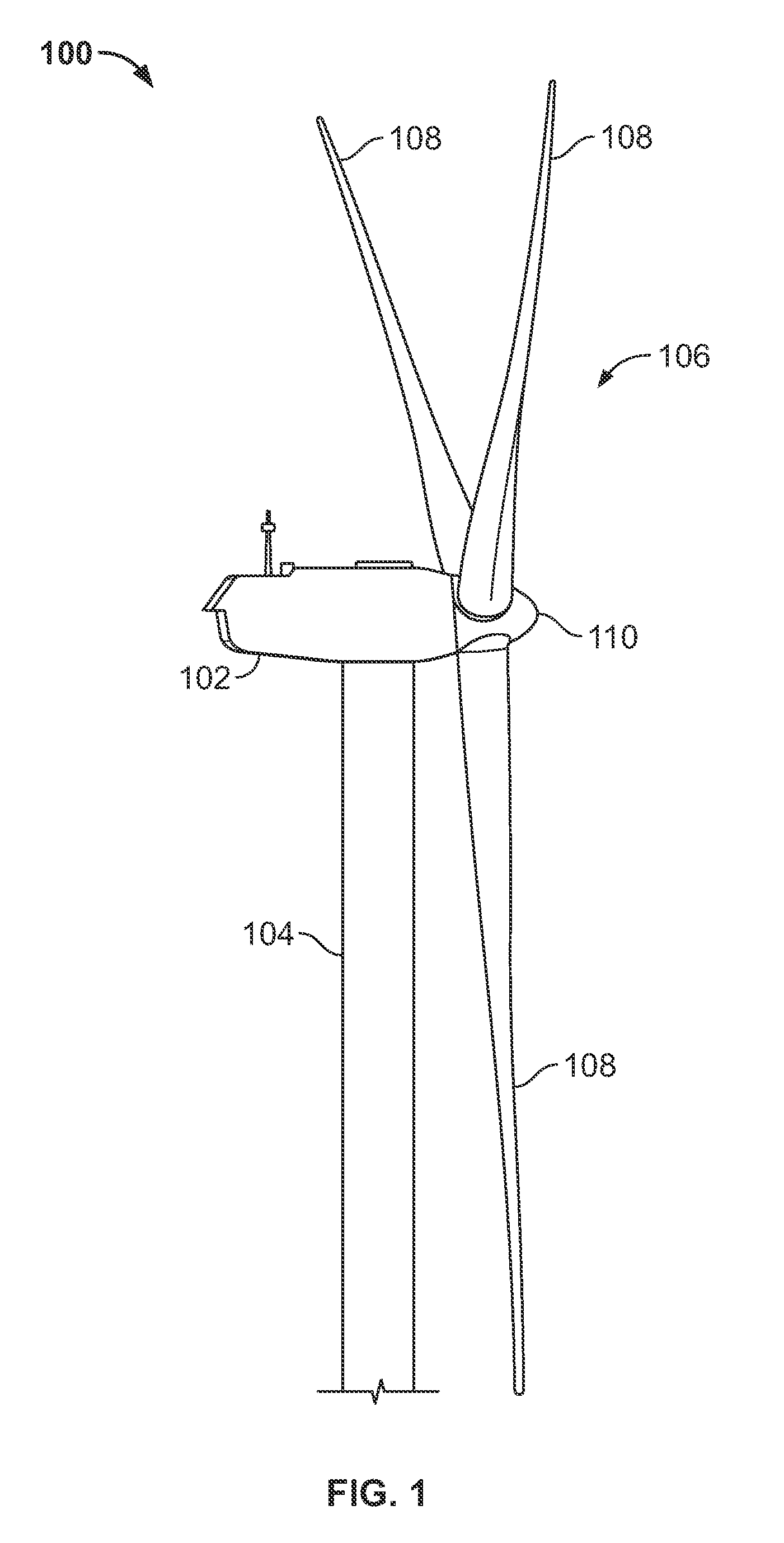
[0029]FIG. 1 shows a wind turbine 100 having a nacelle 102 housing a generator (not shown in FIG. 1). Nacelle 102 is a housing mounted atop a tower 104, only a portion of which is shown in FIG. 1. The height of tower 104 is selected based upon factors and conditions known in the art, and may extend to heights up to 60 meters or more. The wind turbine 100 may be installed on any terrain providing access to areas having desirable wind conditions. The terrain may vary greatly and may include, but is not limited to, mountainous terrain or off-shore locations. Wind turbine 100 also comprises a rotor 106 that includes one or more rotor blades 108 attached to a rotating hub 110. Although wind turbine 100 illustrated in FIG. 1 includes three rotor blades 108, there are no specific limits on the number of rotor blades 108 required by the present disclosure.

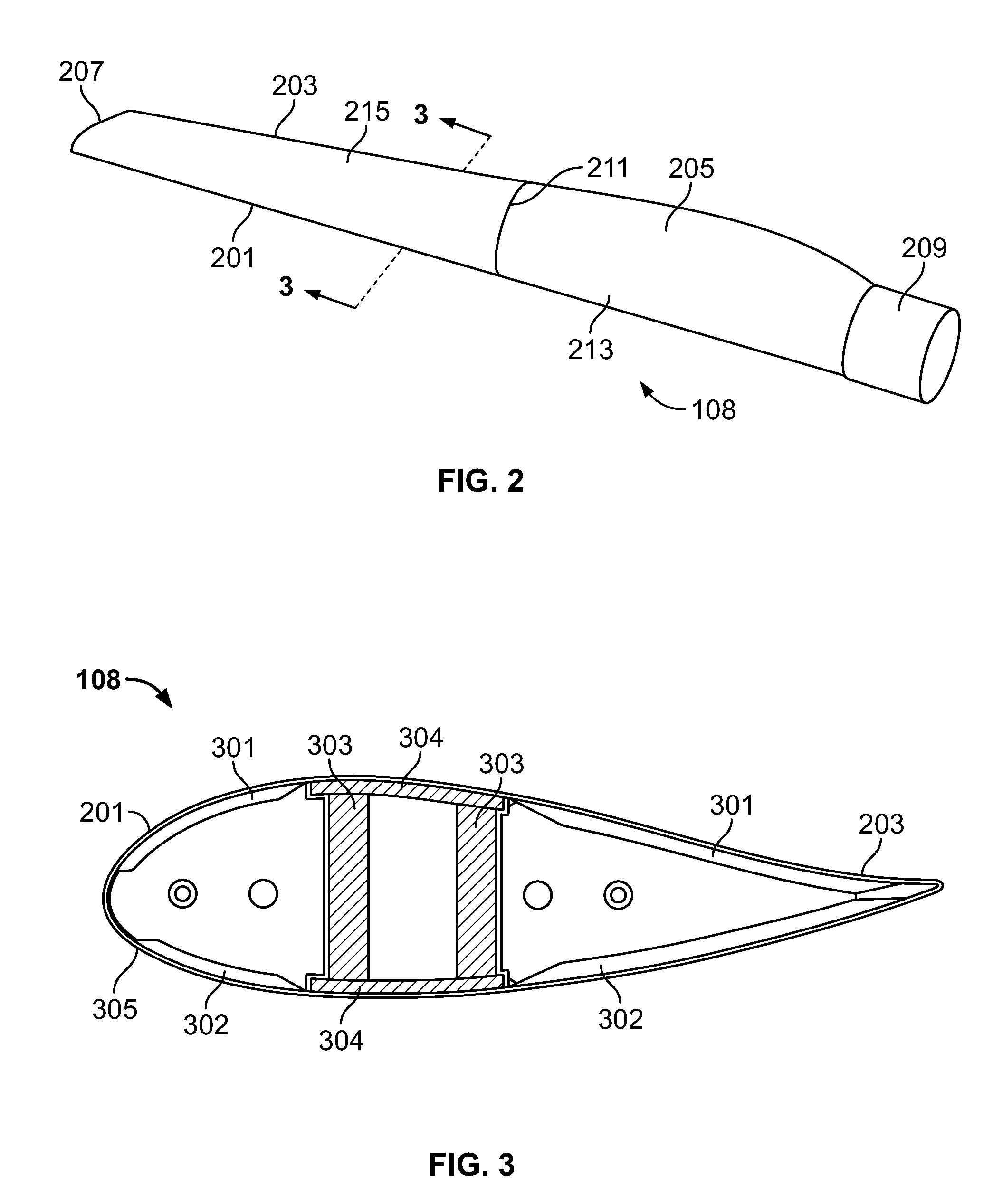
[0030]FIG. 2 illustrates a turbine blade 108 according to an embodiment of the present disclosure having a leading edge 201 and a trailin...


PUM

PropertyMeasurementUnit
Adhesivityaaaaaaaaaa
Areaaaaaaaaaaa
Distributionaaaaaaaaaa

Abstract

A method and system for assembling large wind turbine blades that includes providing a plurality of wind turbine blade segments. An adhesive distribution arrangement is disposed on a surface of at least one of the plurality of the wind turbine blade segments. The adhesive distribution arrangement includes a bonding grid having a plurality of adhesive distribution openings. The wind turbine blade segments are directed together and sufficient adhesive is provided to the bonding grid to substantially fill an area between the wind turbine segments. The adhesive is then cured to form a bonded joint, the bonding grid being incorporated into the bonded joint. A bonding grid for use with the method and system and a segmented wind turbine blade are also disclosed.

Description

FIELD OF THE INVENTION[0001]The present invention is directed to elongated airfoils for use with wind turbines and methods for fabricating elongated airfoils for wind turbines. In particular, the present invention is directed to segmented wind turbine blades and methods for making large, elongated wind turbine blades.BACKGROUND OF THE INVENTION[0002]Recently, wind turbines have received increased attention as environmentally safe and relatively inexpensive alternative energy sources. With this growing interest, considerable efforts have been made to develop wind turbines that are reliable and efficient.[0003]Generally, a wind turbine includes a rotor having multiple wind turbine blades. The wind turbine blades are elongated airfoils configured to provide rotational forces in response to wind. The rotor is mounted to a housing or nacelle, which is positioned on top of a truss or tubular tower. Utility grade wind turbines (i.e., wind turbines designed to provide electrical power to a ...

Claims


Application Information

Patent Timeline
IPC IPC(8): F03D1/06B29C65/54
CPCB29C65/54Y10T29/49339B29C66/1162B29L2031/082B29L2031/085F03D1/0675F05B2230/23F05B2240/302Y02E10/721B29C66/1142Y10T29/49337B29C65/542B29C66/54B29C66/543B29C65/483B29C65/00B29C66/7212B29C66/71Y02E10/72Y02P70/50B29K2307/04B29K2309/08B29K2027/06B29K2063/00B29K2031/00
Inventor LIVINGSTON, JAMIE T.DRIVER, HOWARD
Owner GENERAL ELECTRIC CO
Why Eureka
Try Eureka