Power transmission apparatus for vehicle

a transmission apparatus and vehicle technology, applied in the direction of machines/engines, transportation and packaging, gearing, etc., can solve the problems of giving a sense of discomfort to occupants and following inconvenience, and achieve the effect of suppressing the occurrence of shift shock, preventing the fluctuation of the rotational speed of the main drive power source, and smooth shifting of gears

Inactive Publication Date: 2009-06-18
TOYOTA JIDOSHA KK
View PDF3 Cites 22 Cited by
  • Summary
  • Abstract
  • Description
  • Claims
  • Application Information

AI Technical Summary

Benefits of technology

[0009]In the power transmission apparatus described above, the electric motor is able to control the rotational speed of the main drive power source by changing its rotation, and the control unit executes the control so that the direction in which the rotational speed of the main drive power source is changed is maintained constant throughout a gear-shift, when the gear-shift is a simultaneous gear-shift in which the gear-shift of the first shift unit and the gear-shift of the second shift unit are performed simultaneously and a gear ratio of the first shift unit and a gear ratio of the second shift unit are changed in opposite directions. Therefore, it is possible to prevent fluctuations of the rotational speed of the main drive power source, thereby shifting gears smoothly. That is, it is possible to provide the power transmission apparatus for a vehicle, with which occurrence of shift shock is effectively suppressed.
[0010]In the power transmission apparatus described above, the control unit may control the rotation of the electric motor based on a change in the speed of rotation input in the second shift unit according to a predetermined relationship. In this way, it is possible to prevent fluctuations of the rotational speed of the main drive power source with the use of the electric motor in a practical manner.
[0011]In the power transmission apparatus described above, the first shift unit may have a planetary gear unit that includes a first rotating element connected to the main drive power source, a second rotating element connected to the electric motor, and a third rotating element connected to an input member of the second shift unit. With this structure, it is possible to effectively suppress shift shock in the simultaneous gear shift of the first shift unit and the second shift unit, in the power transmission apparatus that includes the first shift unit which has a practical configuration.

Problems solved by technology

In the process of their studies, the following inconvenience was found.
Such fluctuations may give a sense of discomfort to occupants.

Method used


Image

  • Power transmission apparatus for vehicle
  • Power transmission apparatus for vehicle
  • Power transmission apparatus for vehicle

Examples


first embodiment

[0025]Example embodiments of the invention will be described in greater detail below with reference to the accompanying drawings. First, the invention will be described in detail with reference to the accompanying drawings.

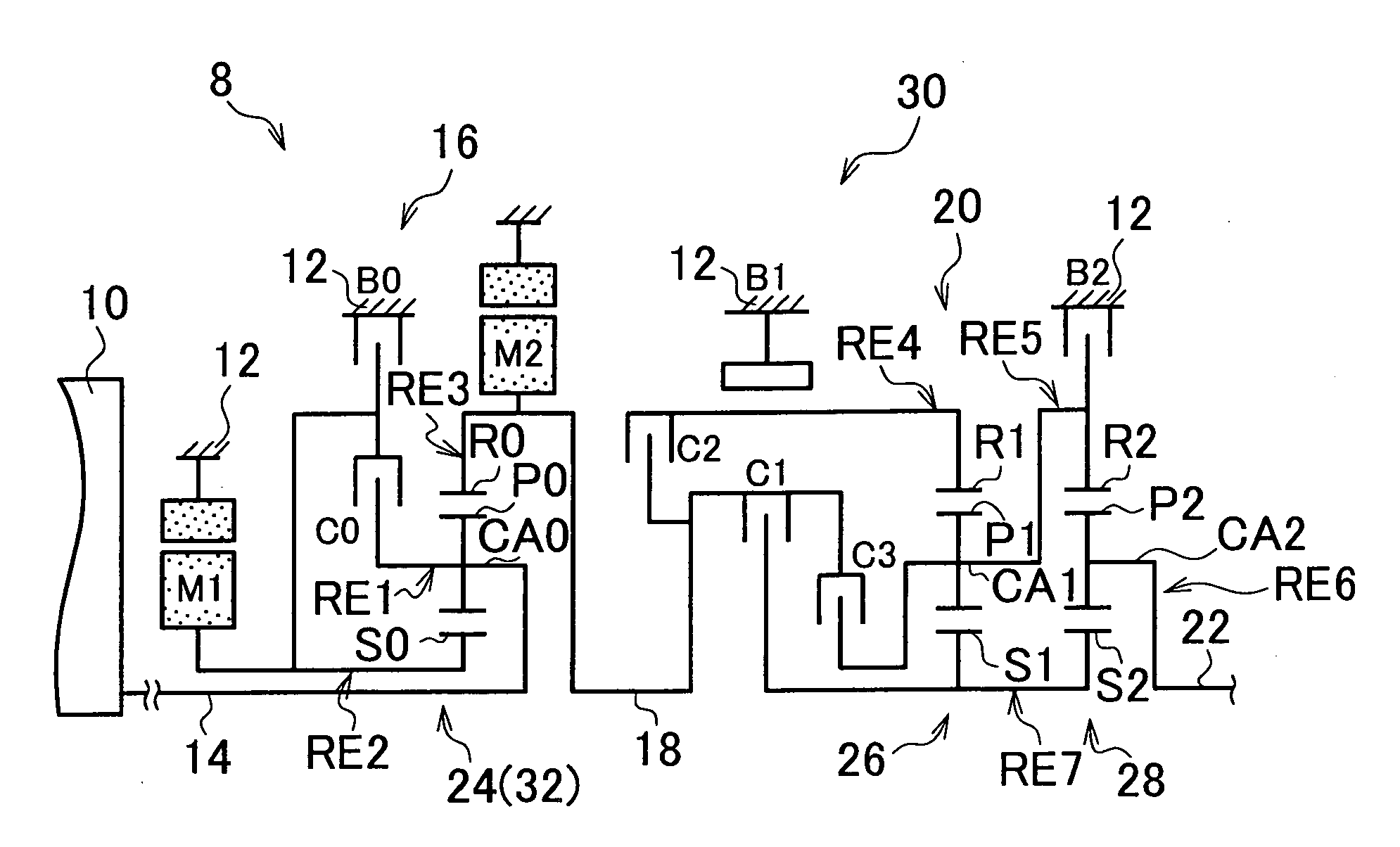
[0026]FIG. 1 is a view schematically showing the structure of a power transmission apparatus 8 for a vehicle that constitutes part of a drive system of a hybrid vehicle according to a first embodiment of the invention. As shown FIG. 1, the power transmission apparatus 8 includes an input shaft 14, a first shift unit 16, a second shift unit 20, and an output shaft 22, all of which are coaxially arranged in tandem inside a transmission case 12 (hereinafter, simply referred to as “case 12”) which is a non-rotating member that is attached to a vehicle body. The input shaft 14 serves as an input rotating member that is either directly connected to an engine 10, which is a main drive power source, or connected to the engine 10 via a pulsation absorbing damper (vibration...

second embodiment

[0099]FIG. 10 is a view schematically showing the structure of a vehicle power transmission apparatus 90 according to the invention. FIG. 11 is an operation chart showing the relationship between shift operations, which are performed when a transmission of the power transmission apparatus 90 in FIG. 10 is made to shift gears in a stepped manner, and the combinations of hydraulic friction application devices that are applied when the shift operations are performed. FIG. 12 is a collinear diagram illustrating the relative rotational speed in each gear when the transmission of the power transmission apparatus 90 in FIG. 10 is made to shift gears in a stepped manner.

[0100]As shown in FIG. 10, the power transmission apparatus 90 according to the second embodiment of the invention includes the first shift unit 16 which has the same structure as that in the first embodiment of the invention and in which the first electric motor M1, the power split mechanism 32 and the second electric motor...


PUM


Abstract

A power transmission apparatus for a vehicle includes a main drive power source; a first shift unit that has an input shaft connected to the main drive power source; a second shift unit; at least one electric motor connected to a rotating element of the first shift unit or a rotating element of the second shift unit so that the rotational speed of the electric motor is changed in accordance with a gear-shift of the first shift unit or the second shift unit, and that is able to control the rotational speed of the main drive power source by changing its rotation; and a control unit that executes control so that the direction in which the rotational speed of the main drive power source is changed is maintained constant throughout a gear-shift, when the gear-shift is a simultaneous gear-shift in which the gear-shift of the first shift unit and the gear-shift of the second shift unit are performed simultaneously and a gear ratio of the first shift unit and a gear ratio of the second shift unit are changed in opposite directions. With the control executed by the control unit, it is possible to effectively suppress occurrence of shift shock.

Description

INCORPORATION BY REFERENCE[0001]The disclosure of Japanese Patent Application No. 2007-323403 filed on Dec. 14, 2007 including the specification, drawings and abstract is incorporated herein by reference in its entirety.BACKGROUND OF THE INVENTION[0002]1. Field of the Invention[0003]The invention relates generally to a power transmission apparatus for a vehicle, which includes a main drive power source, a first shift unit that has an input shaft connected to the main drive power source, a second shift unit, at least one electric motor that is connected to a rotating element of the first shift unit or a rotating element of the second shift unit so that the rotational speed of the electric motor changes in accordance with a gear-shift of the first shift unit or a gear-shift of the second shift unit, and a control unit. More specifically, the invention relates to refinements in the technology for suppressing occurrence of shift shock.[0004]2. Description of the Related Art[0005]There i...

Claims


Application Information

Patent Timeline
Patent Type & Authority Applications(United States)
IPC IPC(8): F16H61/04B60K6/445B60K6/547B60L50/16B60W10/04B60W10/06B60W10/08B60W10/10B60W10/101B60W10/105B60W10/11B60W20/00F02D29/02F16H3/72
CPCF16H3/727Y10T477/676F16H2037/0873F16H61/0437
Inventor TABATA, ATSUSHIKUMAZAKI, KENTAMATSUBARA, TOORU
Owner TOYOTA JIDOSHA KK
Why Eureka
Try Eureka