Surgical instrument assembly

Active Publication Date: 2009-06-18
PREZKOP THOMAS M
View PDF22 Cites 39 Cited by
  • Summary
  • Abstract
  • Description
  • Claims
  • Application Information

AI Technical Summary

Benefits of technology

[0013]It is a further object of the invention to provide a surgical instrument assembly that includes a sheath body (18, 200) that is movable to a LOCK position for enclosing the surgi

Problems solved by technology

Even under ideal circumstances, such as with good lighting and a well positioned patient, a dermatotomy performed with a conventional scalpel may not be optimal when it is performed free hand.
Moreover, a dermatotomy may need to be performed under non-ideal circumstances, e.g. when performed quickly in an emergency, when preformed in a low light level or when performed with the patient poorly positioned and such procedures are even

Method used


Image

  • Surgical instrument assembly
  • Surgical instrument assembly
  • Surgical instrument assembly

Examples


first embodiment

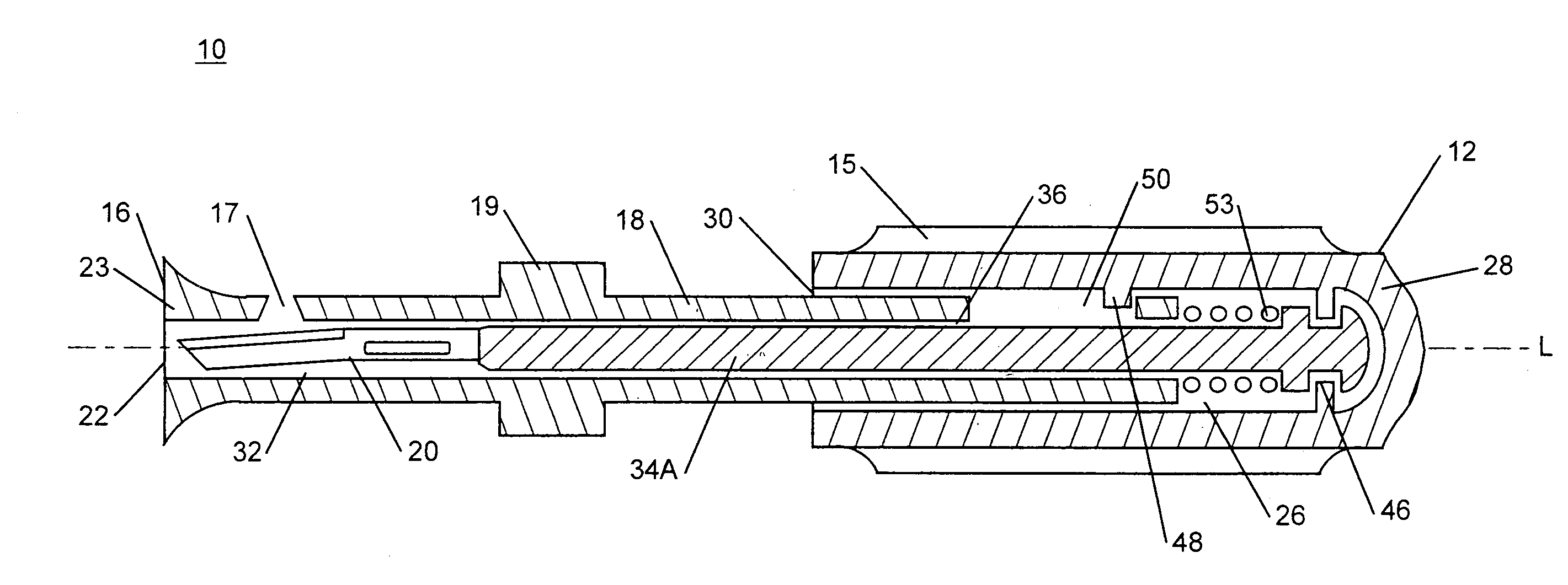
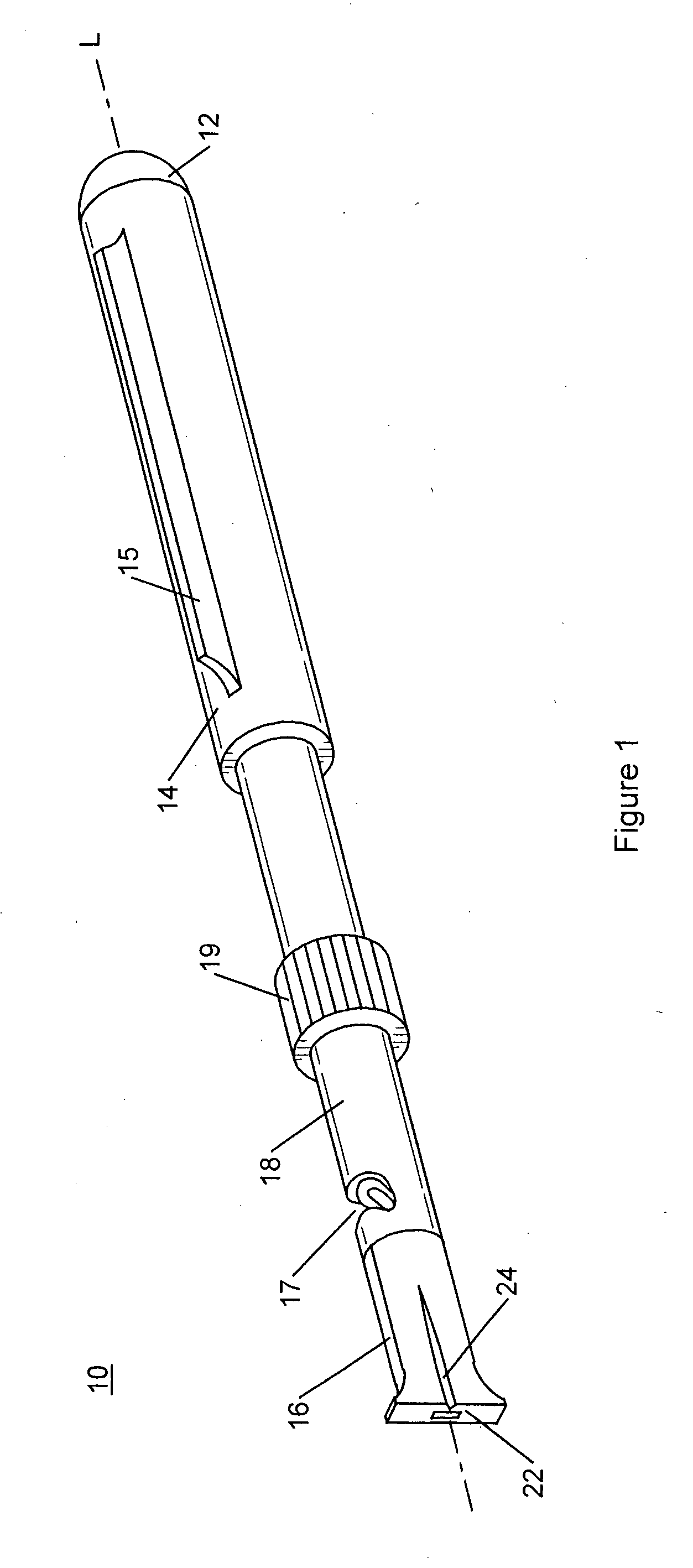
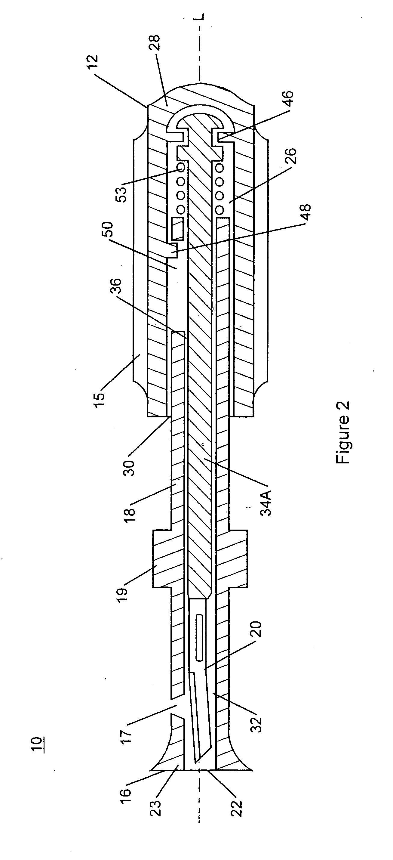
[0039]Referring to FIGS. 1 and 2, FIG. 1 depicts an isometric view of a surgical instrument assembly 10, according to the present invention, and FIG. 2 depicts a section view taken through a longitudinal axis L of the surgical instrument assembly 10. The surgical instrument assembly 10 generally has a back end 12 formed by a handle actuator 14 and a front end 16, opposed to the back end 12, formed by a hollow sheath body 18. A surgical instrument 20, such as a scalpel blade, is fixedly attached to an instrument holder 34A with the instrument holder and scalpel blade 20 supported inside internal hollow cavities of the handle actuator 14 and hollow sheath body 18.

[0040]Referring now to FIGS. 1-4, the instrument holder 34A comprises a longitudinal shaft extending along the instrument longitudinal axis L from the front end 16 to the back end 12. At its front end, the instrument holder 34A is configured to support the surgical instrument 20 in a desired orientation. At its mid section th...

second embodiment

[0048]Turning now to FIGS. 2, 3A, 3B, 4, and the section views of FIGS. 6A-7C, two different embodiments of surgical instrument holders 34A and 34B are shown in isometric view in FIGS. 3A and 3B respectively. The instrument holder 34A installs in the surgical instrument assembly 10, as shown in the section views of FIGS. 2 and 5A-6C. The instrument holder 34B installs in a surgical instrument assembly 11, shown in the section the views of FIGS. 7A-7C.

[0049]Referring to both FIGS. 3A and 3B the instrument holders 34A and 34B include a pointed scalpel blade 68 attached to front ends thereof. The holders 34A and 34B each comprise a solid substantially uniform diameter elongated front shaft portion 62 disposed along the surgical instrument longitudinal axis L and extending between an instrument holding portion 70 and an increased diameter back shaft portion 60. The back shaft portion 60 has a larger diameter than the front shaft portion 62 and includes features on the back end thereof f...


PUM


Abstract

A surgical instrument assembly (10, 11) configurable for performing a dermatotomy in a percutaneous procedure and further configurable for performing cuts in open surgery includes a pointed scalpel blade (68) and a hollow sheath body (18, 200) disposed to encapsulate the pointed scalpel blade (68) inside a longitudinal instrument cavity (32) to protect a user. The hollow sheath body (18, 200) is supported for longitudinal translation with respect to the scalpel blade (68). The hollow sheath (18) may be positioned and locked at a first position to completely encapsulate the scalpel blade (68) inside the instrument cavity (32) for safe handling. Otherwise the hollow sheath body (18, 200) is movable to second and third positions with different lengths of the surgical instrument extending out through a front face (23) of the hollow sheath body (18, 200). A compression spring biases the hollow sheath body (18) toward the first safety position. The instrument is usable to make a precise pierce cut with a consistent cut depth and cut length.

Description

BACKGROUND OF THE INVENTION[0001]1. Field of the Invention[0002]The present invention relates to a multifunctional scalpel usable as a traditional cutting scalpel and usable for dermatotomy or “skin nick” in percutaneous procedures. In particular, the multifunctional scalpel includes elements for engagement to a guide wire, a scalpel blade for safety, positioning the scalpel blade for piercing, and positioning the scalpel blade for conventional cutting.[0003]2. Description of the Related Art[0004]Percutaneous medical procedures use a needle-puncture of the skin to gain access to an internal location such as a blood vessel, hollow internal cavity, internal organ or other internal location. In many applications, percutaneous medical procedures are preferred over “open” surgery which has more complications. Most percutaneous medical procedures are a variation of the Seldinger technique which involves inserting a hollow needle or trocar into a desired internal location and passing a rou...

Claims


Application Information

Patent Timeline
IPC IPC(8): A61B17/3211
CPCA61B17/32093A61B2017/32113A61B2017/320052A61B17/3211
Inventor MUTO, RUDOLPHPREZKOP, THOMAS M.
Owner PREZKOP THOMAS M
Why Eureka
Try Eureka