Numerical controller for controlling five-axis machining apparatus

a technology of numerical controller and machining apparatus, which is applied in the direction of electric programme control, program control, instruments, etc., can solve the problems of long machining time and rough machined shape, and achieve the effect of shortening the machining tim

Active Publication Date: 2009-06-18
FANUC LTD
View PDF27 Cites 27 Cited by
  • Summary
  • Abstract
  • Description
  • Claims
  • Application Information

AI Technical Summary

Benefits of technology

[0021]According to the present invention, the machining time can be shortened while attaining a smooth machined shape in machining a workpiece by a five-axis machining apparatus.

Problems solved by technology

If such program commands are executed, deceleration and acceleration are repeated due to a change in velocity of a rotary axis, posing a problem that the machined shape becomes rough and the machining time becomes long.
Such a problem occurs depending on the machined shape and the type of CAM used.

Method used


Image

  • Numerical controller for controlling five-axis machining apparatus
  • Numerical controller for controlling five-axis machining apparatus
  • Numerical controller for controlling five-axis machining apparatus

Examples


first embodiment

[0036]With reference to a first example of program commands shown in Table 1, the present invention will be described. These program commands are prepared by a CAM described in the description of related art. The technique for generating the program commands per se belongs to the known art.

[0037]In a tool orientation command correcting mode, a maximum number of look-ahead blocks are read in advance as program commands to be corrected until the tool orientation command correcting mode is terminated. A tool orientation command in each block in the look-ahead program commands to be corrected is corrected such that a ratio between a rotary axis motion amount and a linear axis motion amount becomes constant. It should be noted that the maximum number of look-ahead blocks is separately set as a parameter.

[0038]In this example, Gaa is a G code for commanding the tool orientation command correcting mode, and Gbb is a G code for commanding the release of the tool orientation command correcti...

second embodiment

[0058]In the second embodiment, the tool orientation is commanded in terms of a tool orientation vector based on normalized commands I, J, K. A technique for commanding the tool orientation in the form of a tool orientation vector is known, for example, from Japanese Laid-open Patent Publication No. 2003-195917 described in the description of the prior art. The tool orientation vector is calculated from position information on an axis that controls the inclination of tool. In a case for example that the tool inclination is controlled by B- and C-axes, the tool orientation vector is calculated form current positions of the B- and C-axes.

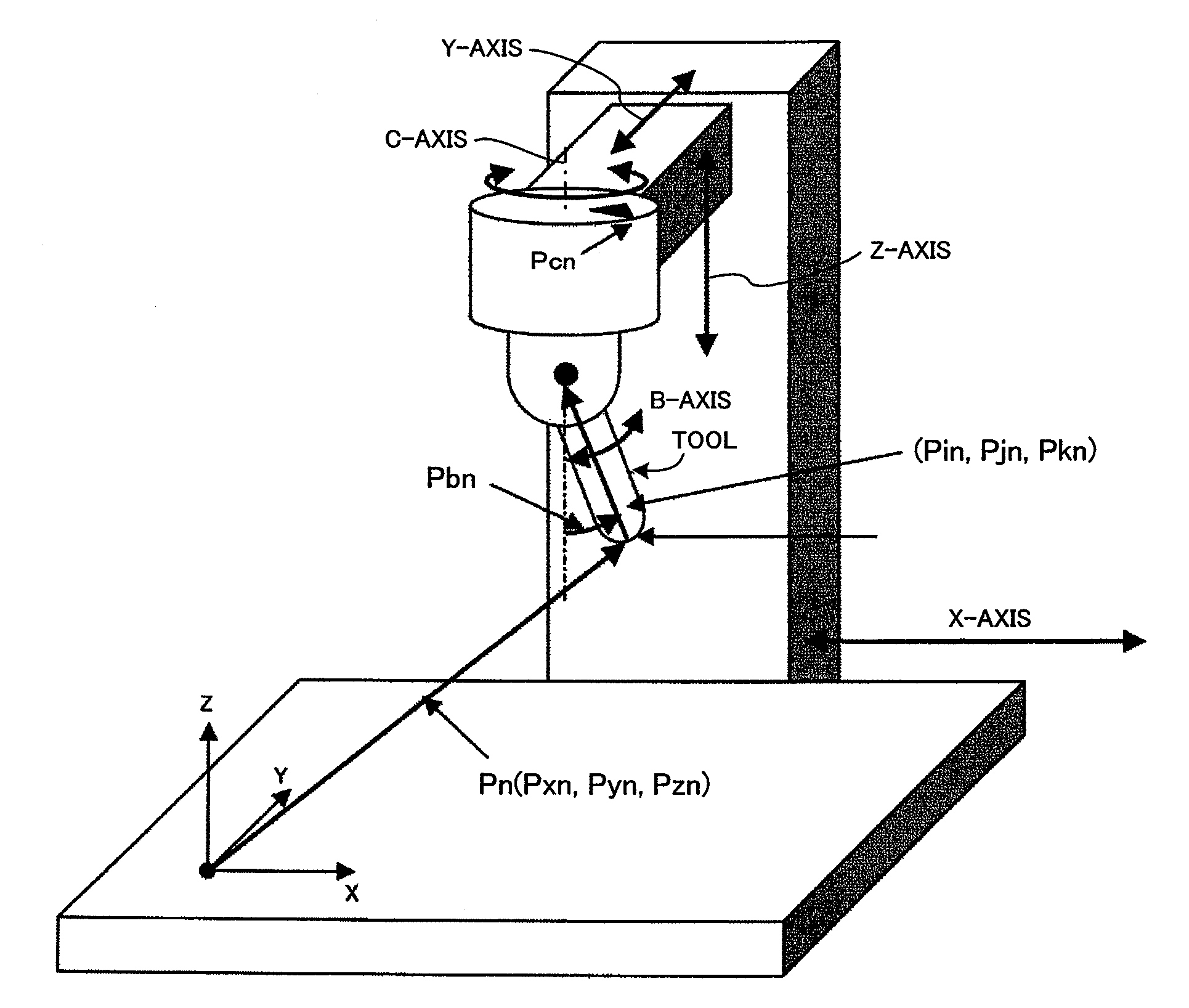
[0059]Assuming that the five-axis machining apparatus is constructed to be a rotary head type shown in FIG. 10, B- and C-axis positions can be calculated from I, J, K commands in accordance with equations (8) and (9) where Pcn varies from 0 degree to 360 degrees and Pbn varies from 0 degree to 90 degrees. It should be noted that n=1 to 10.

Pcn=arctanPj...


PUM


Abstract

A numerical controller for controlling a five-axis machining apparatus, in which a tool orientation command is corrected to thereby attain a smooth machined surface and a shortened machining time. The numerical controller includes command reading means that successively reads a tool orientation command, tool orientation command correcting means that corrects the tool orientation command so that a ratio between each rotary axis motion amount and a linear axis motion amount is constant in each block, interpolation means that determines respective axis positions at every interpolation period based on the tool orientation command corrected by the tool orientation command correcting means, a motion path command, and a relative motion velocity command such that a tool end point moves along a commanded motion path at a commanded relative motion velocity, and means that drives respective axis motors such that respective axis positions determined by the interpolation means are reached.

Description

BACKGROUND OF THE INVENTION[0001]1. Field of the Invention[0002]The present invention relates to a numerical controller for controlling a five-axis machining apparatus having three linear axes and two rotary axes for machining a workpiece mounted on a table.[0003]2. Description of Related Art[0004]To machine a workpiece by a five-axis machining apparatus, the following machining technique has generally been utilized. That is, upon reception of a motion command indicating a motion path for a tool end point and a tool orientation, an interpolation is performed on the motion path for the tool end point based on a commanded relative motion velocity between workpiece and tool, and the tool orientation is also interpolated. As a result, the tool end point moves along the commanded motion path at a commanded velocity, with the tool orientation changing (see, JP2003-195917A, JP2005-174010A, and JP2005-182437A). The above described command and machining technique are called tool end point co...

Claims


Application Information

Patent Timeline
Patent Type & Authority Applications(United States)
IPC IPC(8): G05B19/416
CPCG05B19/404G05B19/4103G05B2219/50336G05B2219/49344G05B2219/50297G05B2219/35158
Inventor OTSUKI, TOSHIAKIIDE, SOICHIROHANAOKA, OSAMUKOGA, DAIJIROU
Owner FANUC LTD
Why Eureka
Try Eureka