
Detector device for detecting component density contained in mixture fuel

a technology of mixture fuel and detector device, which is applied in the direction of instruments, heat measurement, specific gravity measurement, etc., can solve the problem of component density detected by the conventional detector device, and achieve the effect of accurately detecting the density of the component contained in the mixtur

Inactive Publication Date: 2009-06-18
DENSO CORP
View PDF7 Cites 15 Cited by
  • Summary
  • Abstract
  • Description
  • Claims
  • Application Information

AI Technical Summary

Benefits of technology

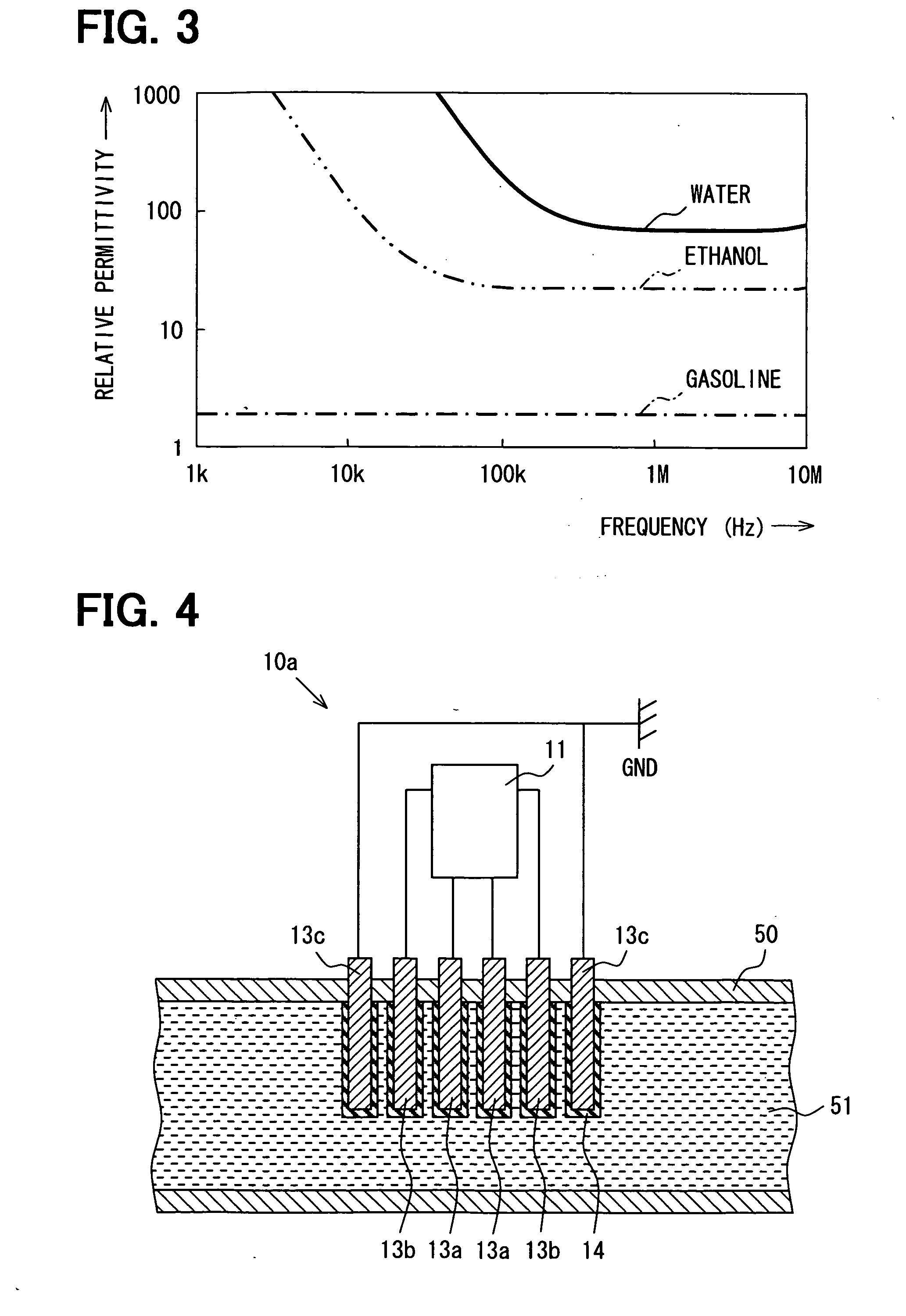
The present invention provides an improved detector device for accurately detecting the density of a component contained in mixture fuel, even when some water is present. The detector device uses a sensor with electrodes that are immersed in the mixture fuel and an electronic device to calculate the density of the component based on the measured permittivities of pure components. The frequencies of an alternating voltage are chosen so that the permittivities of gasoline, ethanol, and water show no change between two frequencies, while the density of the mixture fuel is calculated based on the difference of the permittivities of the mixture fuel and the pure components. The invention can be applied to different mixture fuels, such as those for gasoline and ethanol or for diesel engines. The electrodes may be covered with an insulating film to prevent chemical reactions with the mixture fuel.

Problems solved by technology

However, the following problem is involved in the conventional detector device.
Further, water may be inadvertently mixed with the mixture fuel by a person carrying or handling the mixture fuel.
Therefore, the density of a component detected by the conventional detector device may include an error if water is contained in the mixture fuel.

Method used


Image

  • Detector device for detecting component density contained in mixture fuel
  • Detector device for detecting component density contained in mixture fuel
  • Detector device for detecting component density contained in mixture fuel

Examples


Embodiment Construction

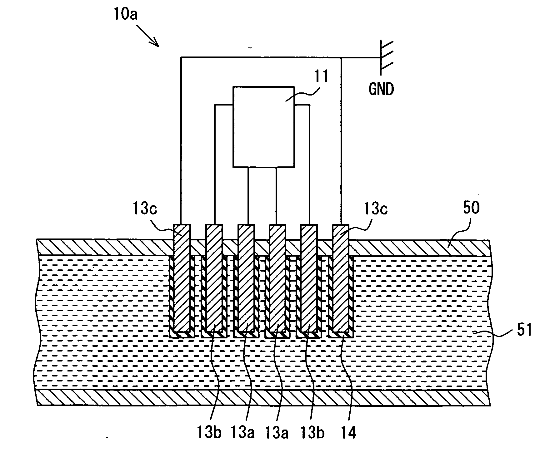
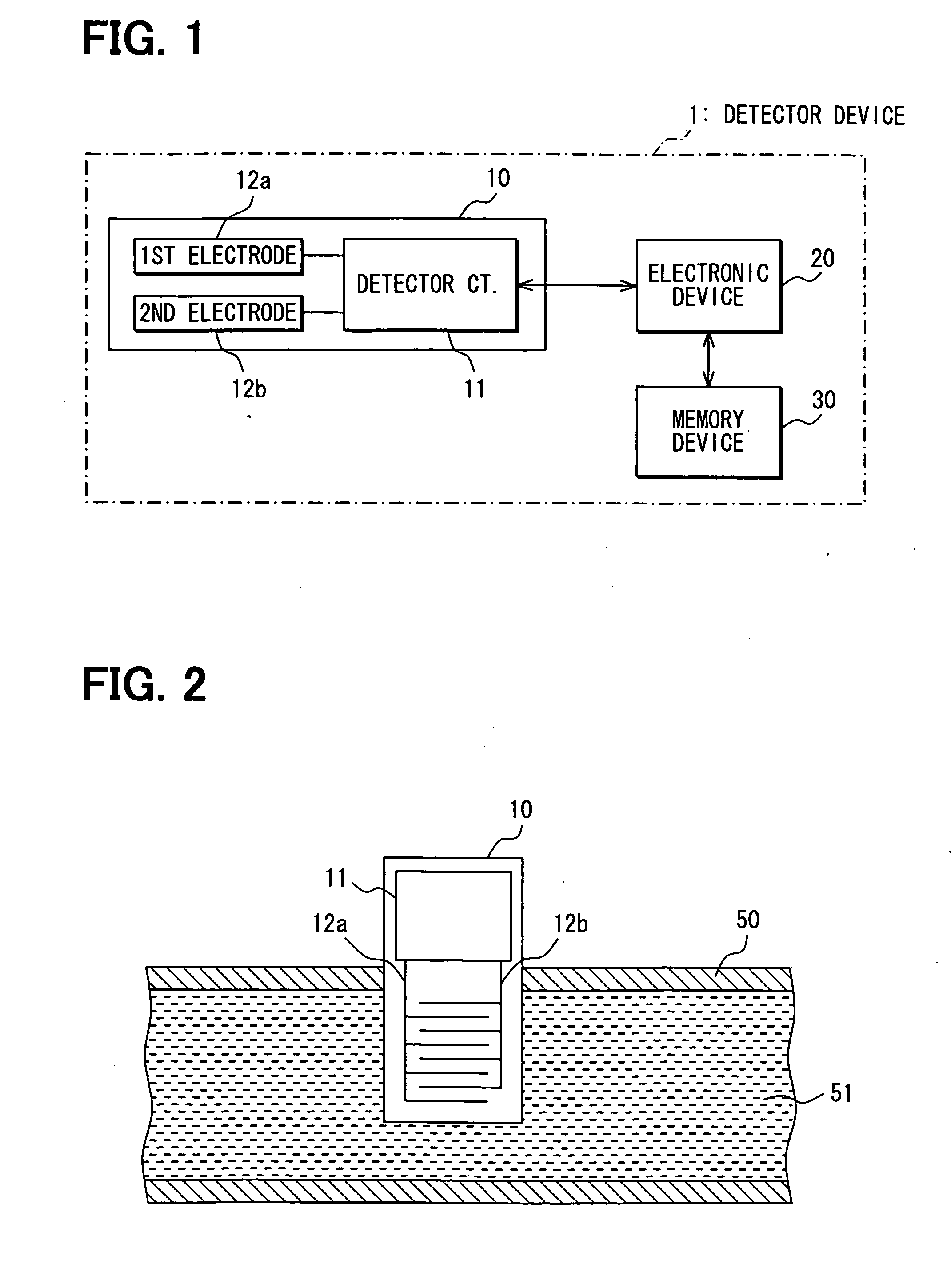
[0018]A preferred embodiment of the present invention will be described with reference to FIGS. 1-3. First, referring to FIGS. 1 and 2, a structure of the detector device 1 for detecting a density of a focused component (such as water) contained in mixture fuel composed of gasoline and ethanol. As shown in FIG. 2, a sensor 10 for detecting a permittivity ε of the mixture fuel 51 is installed in a fuel conduit 50 through which the mixture fuel 51 flows.

[0019]The sensor 10 includes a pair of electrodes 12a, 12b and a detector circuit 11. An alternating voltage V is applied to the pair of electrodes 12a, 12b to measure a capacitance of the pair of electrodes to thereby detect a permittivity ε of the mixture fuel. Each electrode 12a, 12b is formed in a comb-shape, and the pair of electrodes is formed by combining the comb-shaped electrodes in a zigzag form.

[0020]A capacitance C of the pair of electrodes 12a, 12b is determined according to the frequency of the alternating voltage applied...


PUM

PropertyMeasurementUnit
frequencyaaaaaaaaaa
frequencyaaaaaaaaaa
temperatureaaaaaaaaaa

Abstract

A detector device of the present invention detects densities of components, such as gasoline and ethanol, contained in mixture fuel even when some water is included in the mixture fuel. The detector device includes a sensor having a pair or electrodes, an electronic device for calculating the densities and a memory device for storing permittivities of pure components including water measured beforehand. Alternating current having two different frequencies f1, f2 is applied to the pair of electrodes immersed in the mixture fuel to detect the permittivities of the mixture fuel under f1 and f2. The two frequencies, f1 and f2, are so chosen that the premittivities of gasoline and ethanol show no change between f1 and f2, while the permittivitiy of water shows a substantial difference between f1 and f2. The electronic device calculates the densities of the components based on permittivities of the mixture fuel detected by the sensor and those of components stored in the memory device.

Description

CROSS-REFERENCE TO RELATED APPLICATION[0001]This application is based upon and claims benefit of priority of Japanese Patent Application No. 2007-321225 filed on Dec. 12, 2007, the content of which is incorporated herein by reference.BACKGROUND OF THE INVENTION[0002]1. Field of the Invention[0003]The present invention relates to a detector device for detecting a density of a component contained in mixture fuel.[0004]2. Description of Related Art[0005]An example of such a detector device is disclosed in JP-A-5-87764. A conventional detector device including this example will be briefly described. The detector device detects a density of a component such as ethanol contained in mixture fuel composed of, e.g., gasoline and ethanol. A pair of electrodes is immersed in the mixture fuel and alternating voltage is applied to the electrodes to thereby measure a permittivity of the mixture fuel. Since the permittivity of the mixture fuel is determined based on a frequency of the applied alte...

Claims


Application Information

Patent Timeline
Patent Type & Authority Applications(United States)
IPC IPC(8): G06F15/00G01K17/00G01N9/36
CPCG01N27/221
Inventor YOSHIOKA, TETSUOFUKUMURA, KENJIYOSHIDA, TAKAHIKO
Owner DENSO CORP
Learn More