
Infrared gas detector and method of the same

a gas detector and infrared technology, applied in the field of infrared gas detectors, can solve the problem of difficult to enclose the infrared gas detector in a small package, and achieve the effect of preventing the decrease of the sensitivity of the detector and increasing the accuracy of the infrared gas detector

Inactive Publication Date: 2007-10-30
DENSO CORP
View PDF9 Cites 10 Cited by
  • Summary
  • Abstract
  • Description
  • Claims
  • Application Information

AI Technical Summary

Benefits of technology

[0008]It is therefore an object of the present invention to provide an infrared gas detector that accurately detects density of a gas component having absorption wavelength range of infrared light similar to water vapor, and has a small package size. It is another object of the present invention to provide a method of gas detection for giving a correct measurement of gas density.
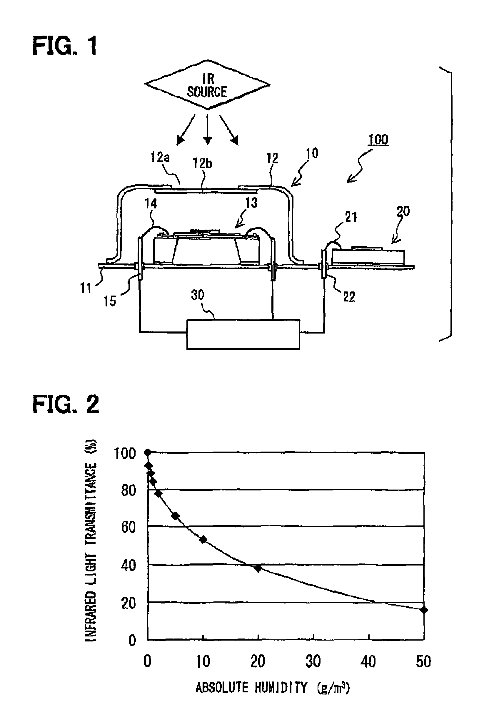
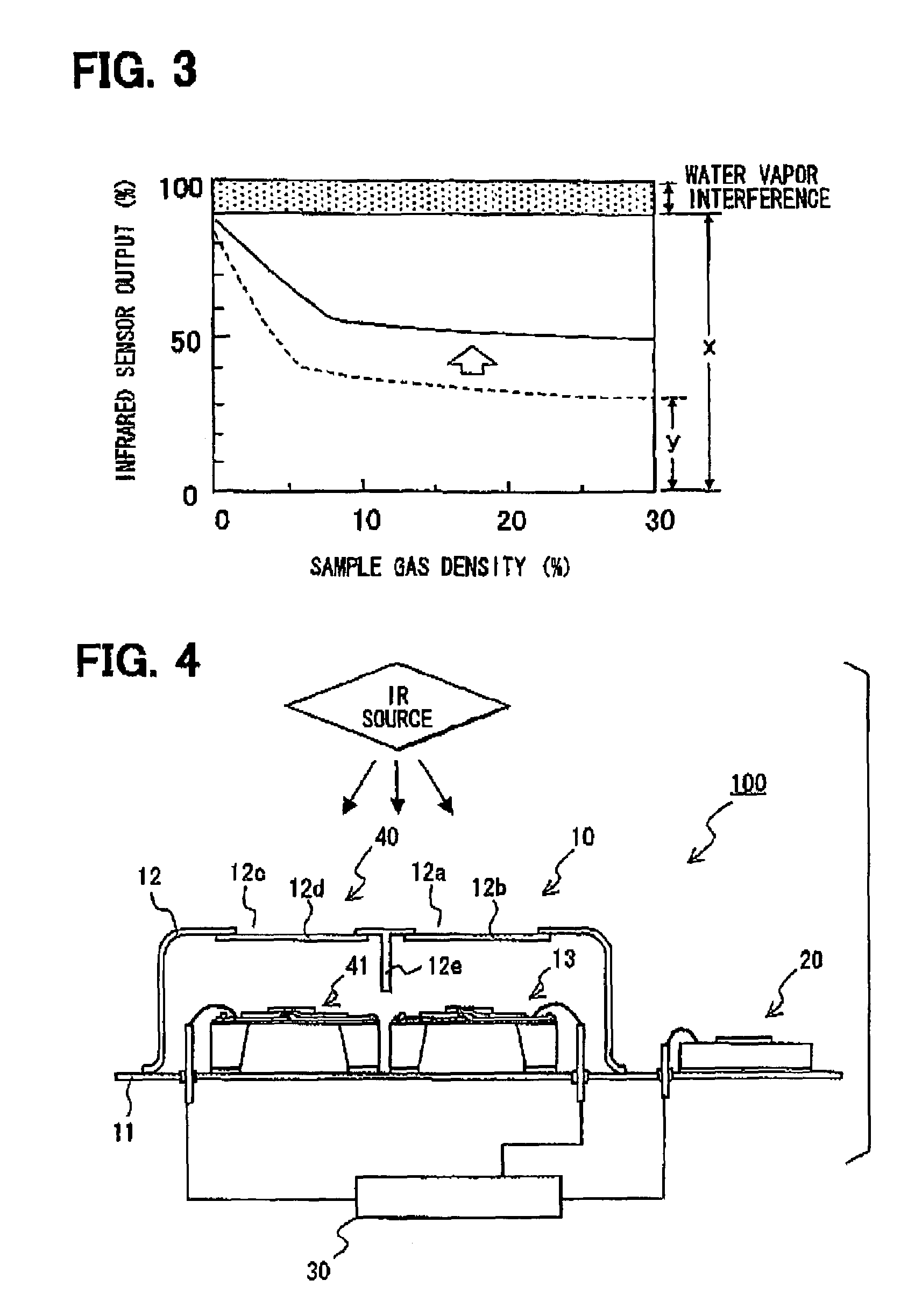
[0010]The infrared gas detector of the present invention is capable of detecting absolute humidity. Therefore, the density of the sample gas is precisely detected by correcting for the interference of water vapor. The infrared gas detector of the present invention has another advantage in that it can be included in a small package because of the omission of plural optical filters, a chopper and a position sensor, even when a humidity detector is added.
[0013]The infrared gas detector may have a reference detector to output a reference signal by absorbing infrared light of a specific wavelength. The wavelength of infrared light for the reference is chosen to be different from the one absorbed by an object sample gas and from the one absorbed by the water vapor. The reference signal is used for correction of the measurement by the detector. In this manner, aging of an infrared light emitting device can be self-checked to prevent decreased sensitivity of the detector.

Problems solved by technology

In this case, the chopper is equipped with a position sensor to detect a filter position that is on the infrared light path at the moment, thereby making it difficult to enclose the infrared gas detector in a small package.

Method used


Image

  • Infrared gas detector and method of the same
  • Infrared gas detector and method of the same
  • Infrared gas detector and method of the same

Examples


Embodiment Construction

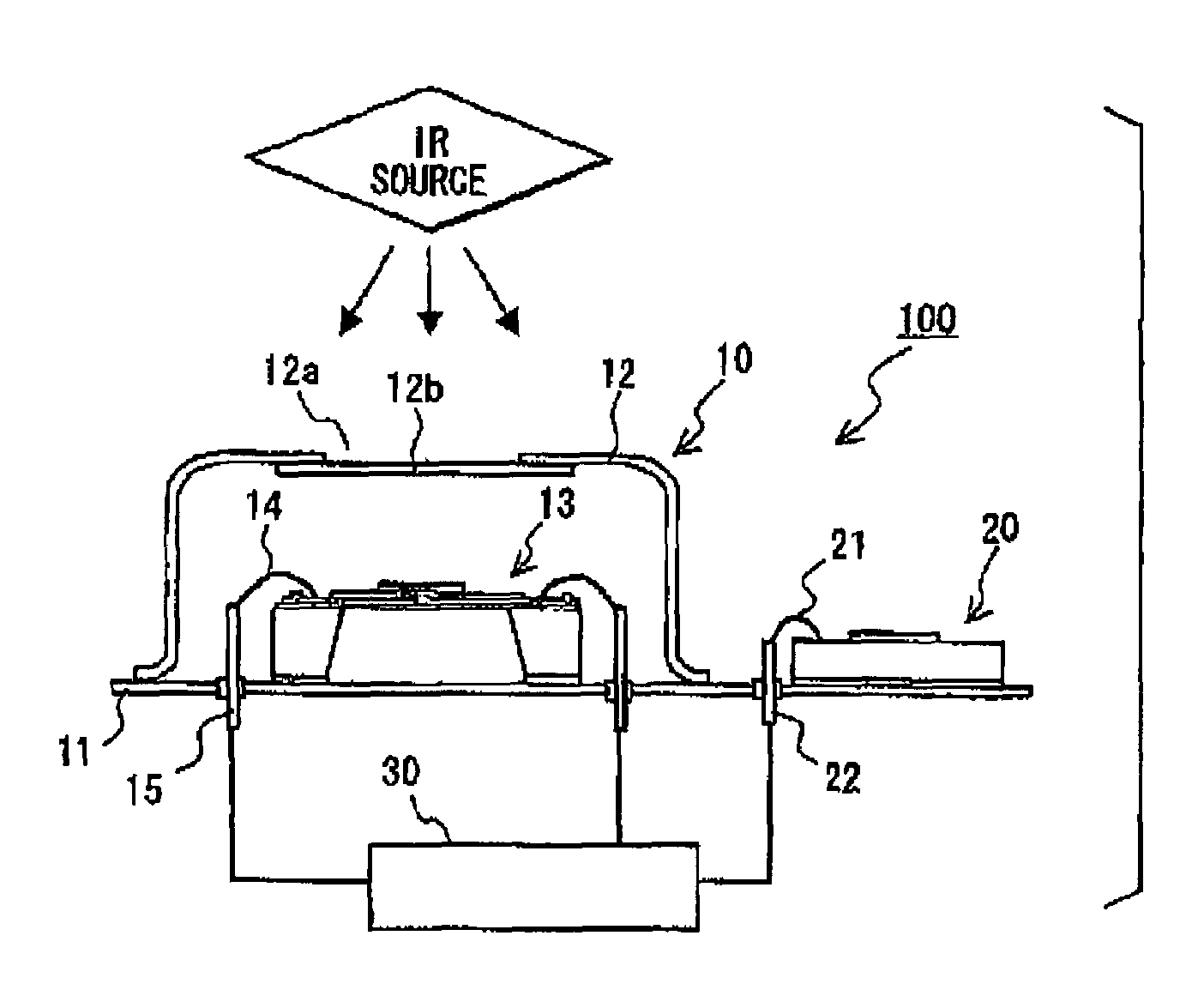
[0020]A schematic view of an infrared gas detector as an embodiment of the present invention is shown in FIG. 1. The infrared gas detector 100 comprises a detector 10 for detecting an infrared light of a specific wavelength, a humidity detector 20 for detecting absolute humidity of water vapor in a sample gas, and a processor 30 for processing signals from the detector 10 and the humidity detector 20.

[0021]The detector 10 includes a pedestal 11, a cap 12 disposed on the pedestal 11, and an infrared light sensor 13 disposed in a space defined by the pedestal 11 and the cap 12.

[0022]The cap 12 is used to limit incoming infrared light by the wavelength of infrared light and to an area on the infrared light sensor 13. Thus, the cap 12 prevents the infrared light from entering the space in the cap 12 except for a window 12a disposed on the cap 12. The window 12a allows the infrared light to be detected by the infrared light sensor 13. The window 12a has a band-pass filter 12b for selecti...


PUM

PropertyMeasurementUnit
wavelengthaaaaaaaaaa
densityaaaaaaaaaa
specific wavelengthaaaaaaaaaa

Abstract

An infrared gas detector for detecting a density of a sample gas includes an infrared light sensor for detecting the density of the sample gas under an influence of water vapor based on an intensity of received infrared light of a specific wavelength, and a humidity sensor for detecting an absolute humidity of the water vapor in the sample gas based on an intensity of the received infrared light of the specific wavelength. The density of the sample gas is determined by correcting for the influence of the water vapor included therein based on the absolute humidity in the sample gas detected by the humidity sensor.

Description

CROSS REFERENCE TO RELATED APPLICATION[0001]This application is based upon and claims the benefit of priority of Japanese Patent Application No. 2004-109379 filed on Apr. 1, 2004, the contents of which is incorporated herein by reference.FIELD OF THE INVENTION[0002]The present invention relates to an infrared gas detector having an infrared sensor, and, more specifically to an infrared gas detector having a correction function for water vapor interference.BACKGROUND OF THE INVENTION[0003]In recent years, infrared gas detectors have been developed for detection of gas density by sensing absorption of infrared light of specific wavelengths. For example, Japanese Patent Document JP-A-2003-50203 discloses an infrared gas detector having an infrared sensor for detecting absorption of infrared light.[0004]The infrared gas detector (non-dispersive infrared gas detector) is equipped with multiple optical filters for filtering infrared light of specific wavelengths (passing infrared light of...

Claims


Application Information

Patent Timeline
Patent Type & Authority Patents(United States)
IPC IPC(8): G01N21/00G01N21/61
CPCG01N21/3554
Inventor UCHIDA, KOUJIYOSHIDA, TAKAHIKO
Owner DENSO CORP
Learn More