Vacuum insulated switchgear

a switchgear and vacuum insulation technology, applied in the direction of switchgear arrangements, switchgear arrangements, air-break switches, etc., can solve the problems of dielectric breakdown, cannot be said, etc., and achieve the effect of suppressing dielectric breakdown

Inactive Publication Date: 2009-06-25
HITACHI LTD
View PDF3 Cites 9 Cited by
  • Summary
  • Abstract
  • Description
  • Claims
  • Application Information

AI Technical Summary

Benefits of technology

[0023]The present invention can suppress dielectric breakdown that may be caused when a high electric field is applied to

Problems solved by technology

However, it cannot be said that the switchgear described in Patent Document 1 is sufficiently considered against dielectric breakdown that may be caused by the use of the solid insu

Method used


Image

  • Vacuum insulated switchgear
  • Vacuum insulated switchgear
  • Vacuum insulated switchgear

Examples


Embodiment Construction

[0039]Embodiments of a vacuum insulated switchgear by applying the present invention will be described with reference to the drawings. In the description that follows, like elements are denoted by like reference numerals to eliminate duplicate explanation.

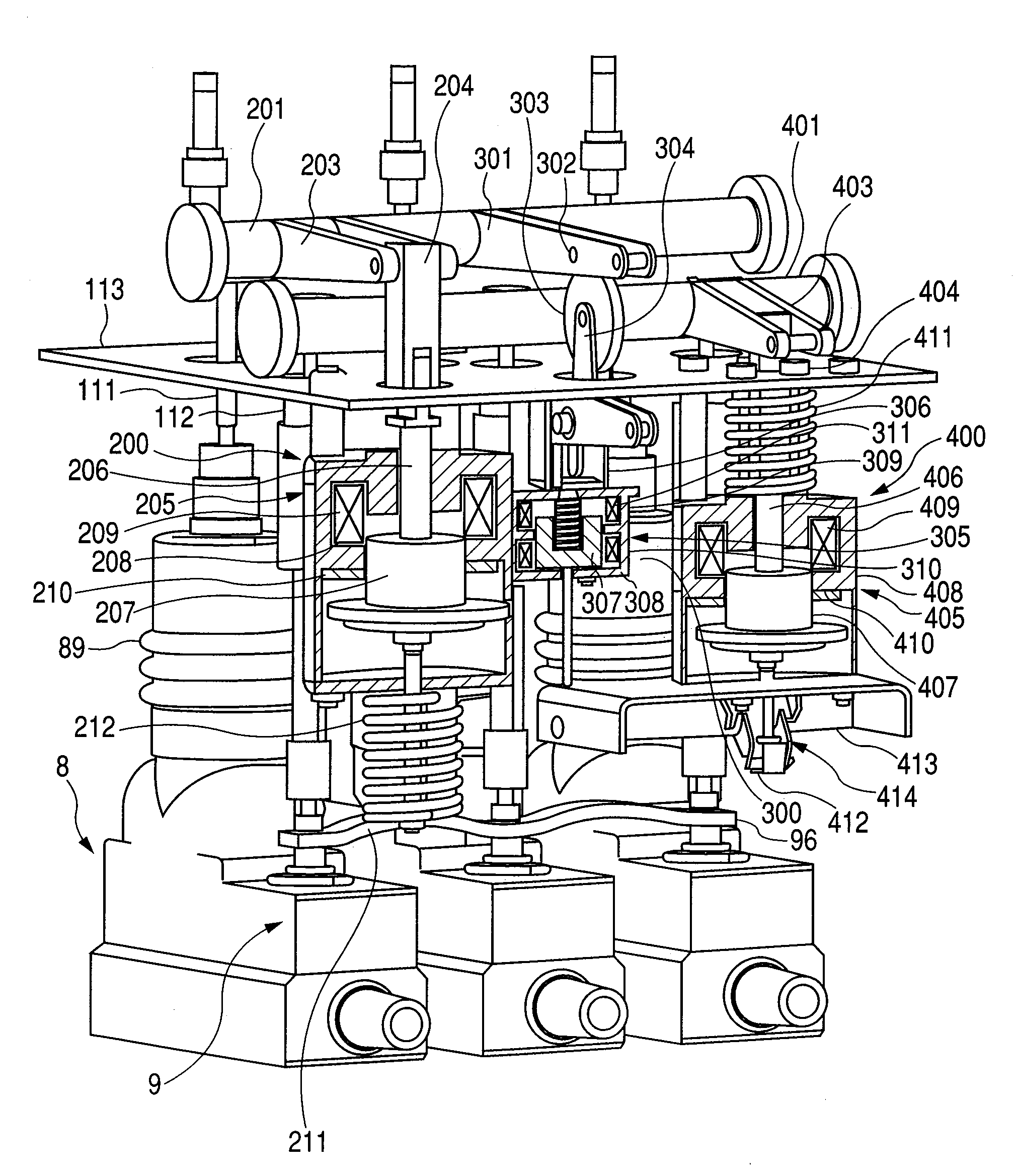
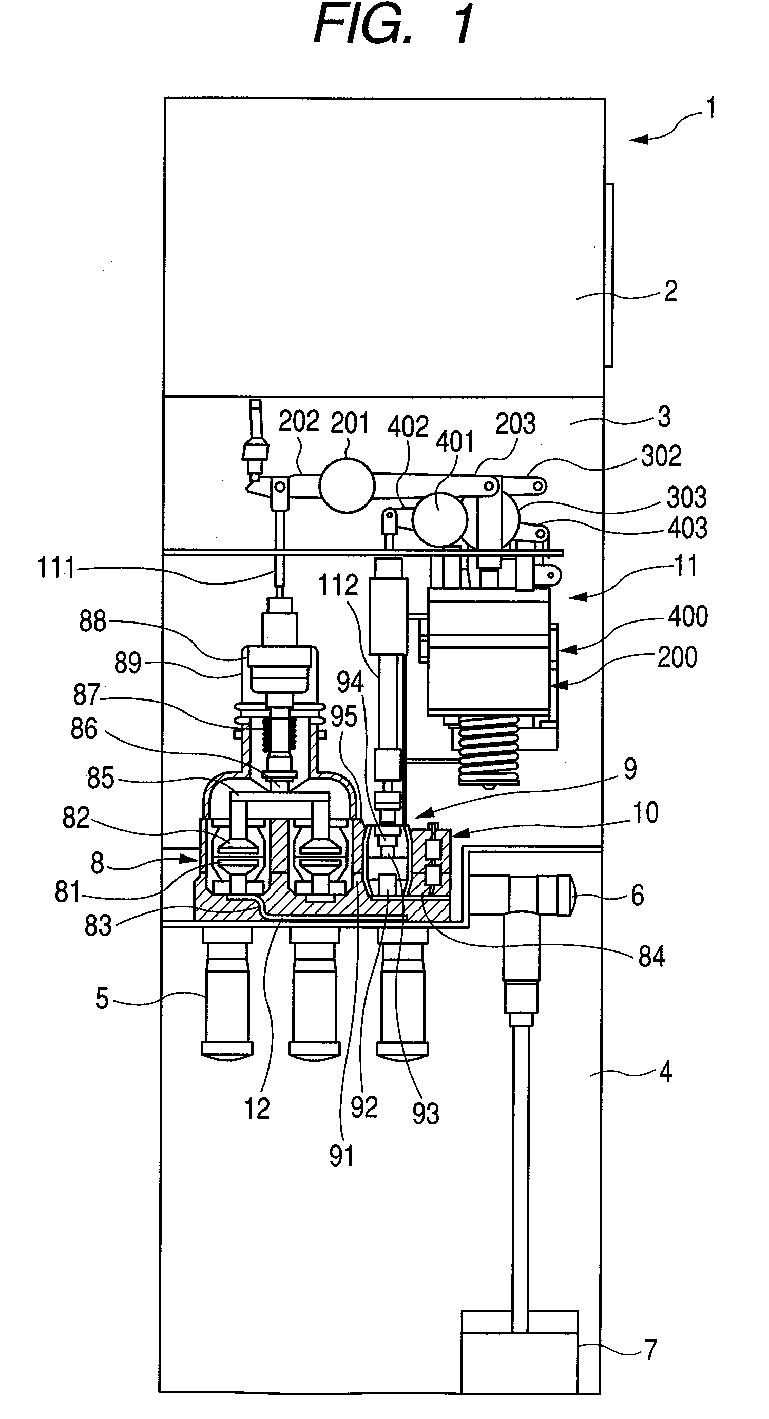
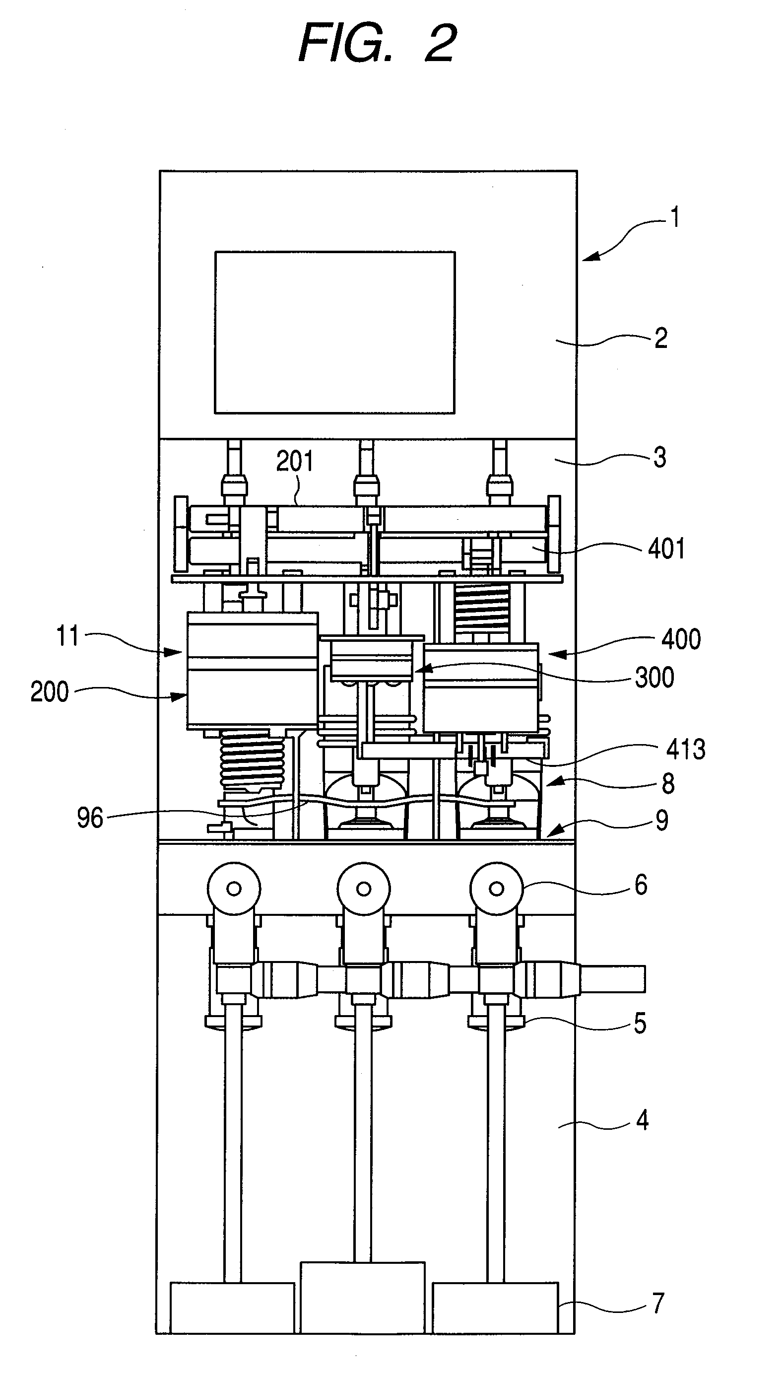
[0040]FIGS. 1 to 3 are a side view, a front view, and a perspective view of an embodiment of the present invention in which the inventive vacuum insulated switchgear is used as a feeder panel. FIG. 4 is a diagram of an electric circuit in the vacuum insulated switchgear. The interior of a container 1 of the vacuum insulated switchgear in this embodiment is divided into a low-pressure control section 2, a high-pressure switch section 3, and a bus and cable section 4, when viewed from the top.

[0041]Disposed in the high-pressure switch section 3 are a vacuum double-break three-position type switch (vacuum double-break three-position type breaking and disconnecting switch (BDS)) 8, an earthing switch (ES) 9 having a vacuum closed conta...


PUM


Abstract

A vacuum insulated switchgear having a vacuum container, a fixed contact disposed in the vacuum container, a movable contact disposed in the vacuum container capable of being in contact with or out of contact with the fixed contact, a driving mechanism for driving the movable contact in directions to contact with and out of contact with the fixed contact, a resin portion molded around the vacuum container, an insulative bushing for covering a pulled-out portion of a conductor connected to the fixed contact and for extending from the molded resin portion, and a cable head insulating member for covering a conductor of a cable head connected to the conductor at the pulled-out portion and an outer surface of the cable head insulating member being earthed, characterized in that:
    • an earthed conductive member is embedded at least at a position opposite to an end of the cable head insulating member in the bushing.

Description

CLAIM OF PRIORITY[0001]The present application claims priority from Japanese patent application JP 2007-331114 filed on Dec. 21, 2007, the content of which is hereby incorporated by reference into this application.BACKGROUND OF THE INVENTION[0002]1. Field of the Invention[0003]The present invention relates to a vacuum insulated switchgear, specifically, to a technology for suppressing dielectric breakdown of a vacuum insulated switchgear that uses a solid insulation method.[0004]2. Description of Related Art[0005]A power receiving facility has a closed power distribution panel (referred to below as a switchgear at appropriate places) that includes a vacuum breaker for shutting off load current and fault current, a disconnecting switch and an earthing switch for securing safety for an operator who services a load, a detector for detecting a voltage and current in the system, a protective relay, and the like.[0006]This type of switchgear is insulated in various ways; in addition to co...

Claims


Application Information

Patent Timeline
IPC IPC(8): H01H33/666
CPCH02B13/01H02B13/0354H02G15/064H02B13/075H02B13/0358H01H2033/66276H01H2239/038
Inventor OZAWA, HIROYUKITSUCHIYA, KENJIKOBAYASHI, MASATOMORITA, AYUMU
Owner HITACHI LTD
Why Eureka
Try Eureka