
Portable laptop stand

a laptop stand and portable technology, applied in the field of laptop stand, can solve the problems of increasing the chance of malfunction and breakage, difficult to transport, and high manufacturing cost of many current adjustable and collapsible laptop stands, and achieve the effects of improving flexibility, easy manipulation, and improving flexibility of clamping or gripping ends

Inactive Publication Date: 2009-06-25
KIM SANG KWON
View PDF41 Cites 298 Cited by
  • Summary
  • Abstract
  • Description
  • Claims
  • Application Information

AI Technical Summary

Benefits of technology

[0009]Another objective of the present invention is to provide a portable laptop stand that is relatively inexpensive to manufacture.
[0010]Another objective of the present invention is to provide a portable laptop stand that is comprised of pliable material that is relatively easy to manipulate, in particular, to bend, fold and collapse.
[0011]Another objective of the present invention is to provide improved flexible clamping or gripping ends which have increased contact surface that conforms to the instrument body edge so as to reduce the chance of unwanted instrument body slippage.

Problems solved by technology

However, many adjustable and collapsible laptop stands involve numerous moving parts including a variety of pins, bolts, screws, and other moving parts that increase the chance of malfunction and breakage.
Additionally, many current adjustable and collapsible laptop stands are expensive to manufacture and difficult to transport due to the size and weight of the laptop stands.
While these devices may be suitable for the particular purpose to which they address, they are not suitable for incorporating the advantages of a fully adjustable and collapsible laptop stand that has few, if any, moving parts to reduce malfunction and breakage and is relatively lightweight to increase portability and is relatively inexpensive to manufacture.

Method used


Image

  • Portable laptop stand
  • Portable laptop stand
  • Portable laptop stand

Examples


Embodiment Construction

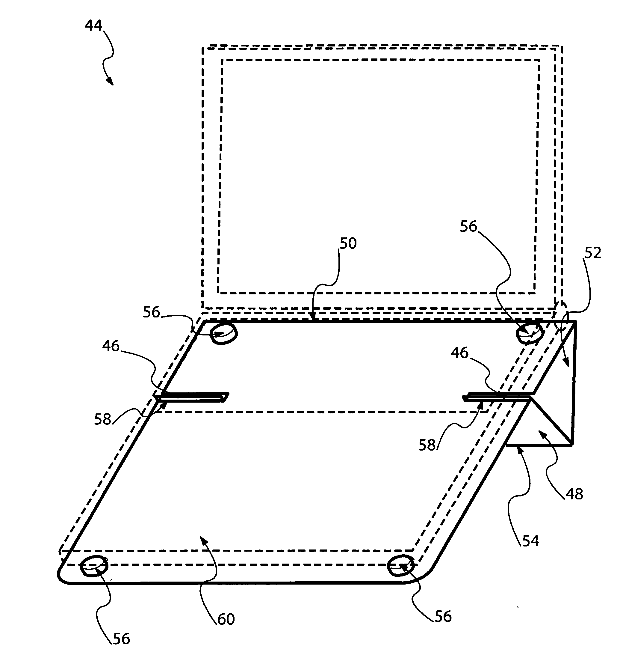
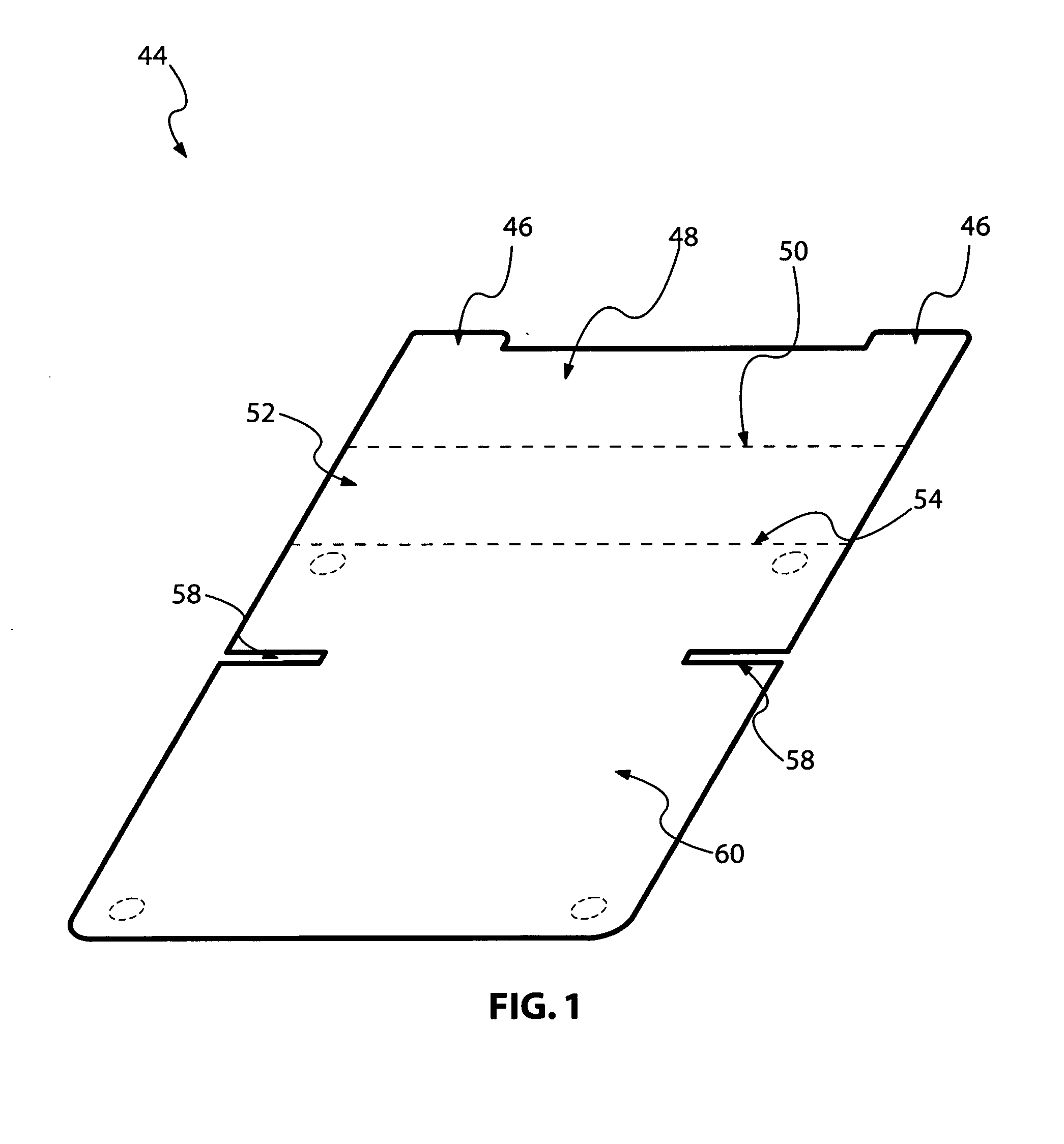
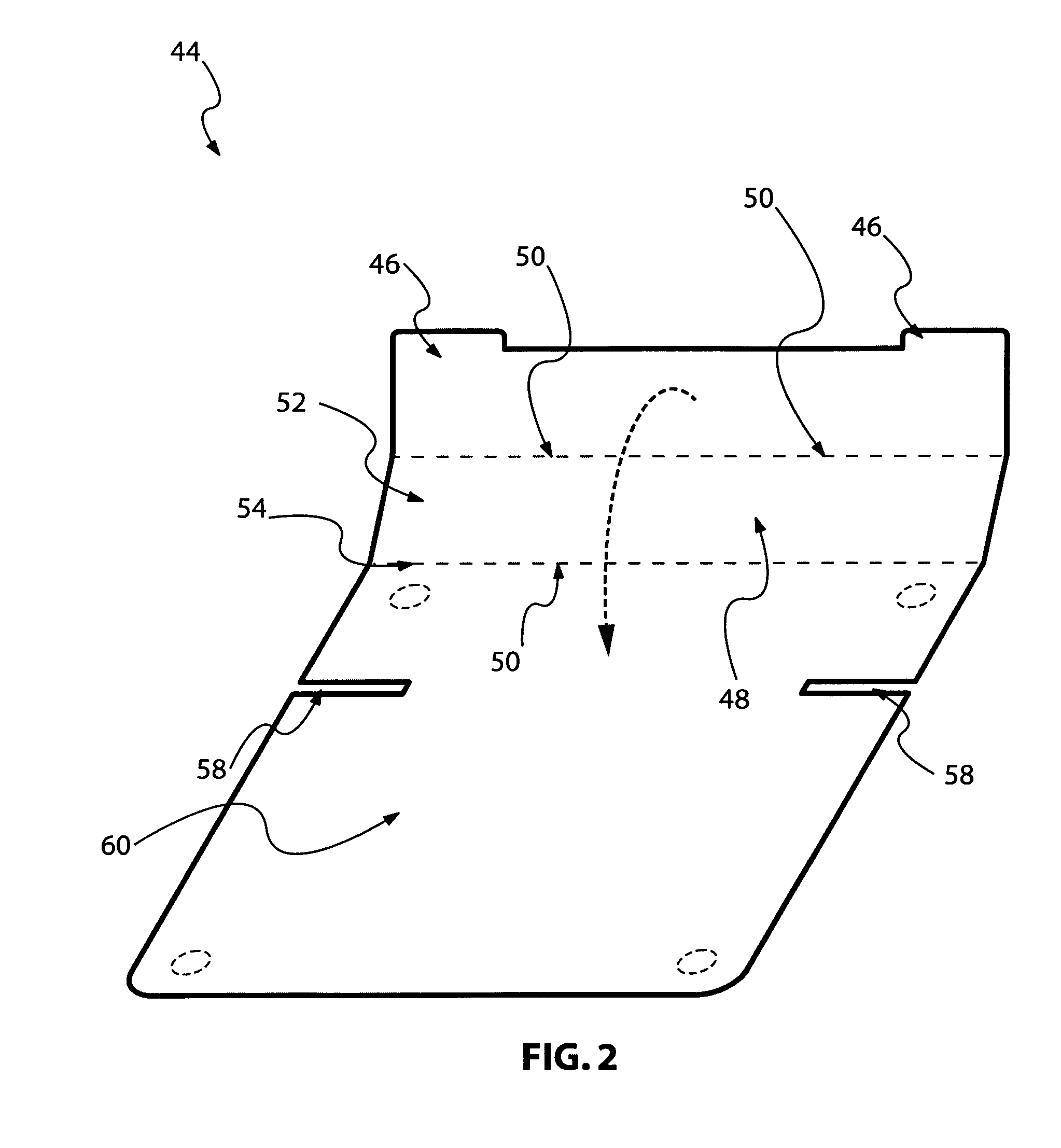
[0031]Turning now to the embodiment of FIG. 1, the portable laptop stand 44 of the present invention comprises a generally rectangular flat board 60 with a distal end and proximate end, said board having a first portion 48 and a second portion 52 that is pivotably coupled to said first portion 48. The first portion 48 having a longitudinal axis that is perpendicular to the longitudinal axis of the board and wherein the second portion 52 also having a longitudinal axis that is perpendicular to the longitudinal axis of the board. As shown in FIG. 2, a first and second crease 50 and 54 allows the first portion 48 of being capable of folding back towards the main body 60 and contacting the main body 60. In typical use, the user would urge the first portion 48 containing a first attachment means 46 onto the second attachment means 58 to securely connect the first portion 48 to the main body 60 as clearly illustrated in FIG. 3. In one preferred embodiment, the first attachment means compr...


PUM


Abstract

A portable laptop stand comprising a generally rectangular flat board having a longitudinal axis perpendicular to a width of the board; said board having a distal end; said board having a proximal end; said board having a first portion, a second portion pivotably coupled to the first portion, and a main body pivotably coupled to the second portion; wherein the first portion has a longitudinal axis that is perpendicular to the longitudinal axis of the board; wherein the second portion has a longitudinal axis that is perpendicular to the longitudinal axis of the board; wherein said first portion is capable of folding back towards the main body and contact the main body. The board having a first attachment means disposed on the first portion; and a second attachment means disposed on the main body to detachably attach to said first attachment means.

Description

BACKGROUND OF INVENTION[0001]1. Field of the Invention[0002]The present invention generally relates to laptop computer stands, in particular, to a simple, portable, lightweight and relatively inexpensive laptop computer stand.[0003]2. Description of the Prior Art[0004]A laptop stand is commonly used to support a personal laptop computer to increase the comfortability and stability of use of the laptop computer by the user. As one can appreciate, many configurations exists regarding different types of laptop stands that include such prior registered patents such as U.S. Pat. No. 5,209,452 (Goldberg), U.S. Pat. No. 6,913,238 (Bakker et al.), U.S. Pat. No. 6,819,548 (Hillis et al.) and U.S. Pat. No. 6,352,233 (Barberich), all hereby incorporated by reference.[0005]However, many adjustable and collapsible laptop stands involve numerous moving parts including a variety of pins, bolts, screws, and other moving parts that increase the chance of malfunction and breakage. Additionally, many ...

Claims


Application Information

Patent Timeline
IPC IPC(8): F16M11/00
CPCF16M13/00A47B23/044A47B2220/0019F16M11/22F16M11/38A47B2200/04G06F1/16G06F1/1637G06F1/166G06F1/20H05K7/20
Inventor KIM, SANG KWON
Owner KIM SANG KWON
Learn More