Anti-rollaway device for trucks and equipment with fluid and electrically actuated brakes

a technology of fluid and electrically actuated brakes, which is applied in the direction of braking systems, braking components, transportation and packaging, etc., can solve the problem of vehicles inadvertently moving without an operator

Active Publication Date: 2009-06-25
ACCARDI THOMAS
View PDF11 Cites 11 Cited by
  • Summary
  • Abstract
  • Description
  • Claims
  • Application Information

AI Technical Summary

Benefits of technology

[0021]The device can include a third switch operative for controlling the response of the solenoid valve to the signal output by the speed control as a function of a change in a fluid pressure supplied to a service brake of the vehicle.
[0022]When (1) the speed control is outputting the signal, (2) the first switch is in a first state in response to the passage of pressurized fluid to the parking brake of the vehicle via the parking control valve and the solenoid valve, and (3) the second switch is in a first state in response to the operator being absent from the predetermined location in the vehicle, in response to a predetermined change in the fluid pressure supplied to the service brake of the vehicle, the third switch can change state whereupon the solenoid valve becomes responsive to the signal output by the speed control for terminating the supply of pressurized fluid to the parking brake of the vehicle.
[0023]Another embodiment of a vehicle anti-rollaway device for use on a vehicle equipped with a parking control valve operative for controlling the supply of pressurized fluid to a parking brake of the vehicle includes a speed control operative for outputting a signal when the speed of the vehicle is at or below a predetermined speed; a solenoid valve responsive to the signal output by the speed control for controlling the supply of pressurized fluid to the parking brake of the vehicle; and a first switch operative for controlling the response of the solenoid valve to the signal output by the speed control as a function of the presence and absence of an operator at a predetermined location in the vehicle, wherein, in response to the operator moving from the predetermined location in the vehicle when pressurized fluid is being supplied to the parking brake of the vehicle via the solenoid valve and the parking control valve, the first switch changes state whereupon the solenoid valve terminates the supply of pressurized fluid to the parking brake of the vehicle.
[0024]The device can further include a second switch for controlling the response of the solenoid valve to the signal output by the speed control as a function of a supply of pressurized fluid to a service brake of the vehicle, wherein in response to the supply and absence of the pressurized fluid to the service brake of the vehicle, the second switch causes the solenoid valve to be respectively not responsive and responsive, or vice versa, to the signal output by the speed control.
[0025]The device can further include a second, fluid-pressure controlled switch operative for controlling the response of the solenoid valve to the signal output by the speed control as a function of the supply of pressurized fluid to the parking brake of the vehicle, wherein in response to the supply and absence of pressurized fluid being supplied to the parking brake of the vehicle, the second switch causes the solenoid valve to be responsive and not responsive, or vice versa, to the signal output by the speed control.
[0026]The first switch, the second switch and a control input of the solenoid valve can be connected in series with the signal output by the speed control. The solenoid valve can be responsive to the signal output by the speed control received at the control input of the solenoid valve for controlling the flow of pressurized fluid to the parking brake of the vehicle.

Problems solved by technology

In many instances, failure to set the parking brake has resulted in the vehicle inadvertently moving without an operator being present, a so-called “rollaway” condition.
In many instances of rollaway, it is not uncommon for such vehicles to collide with other vehicles, structures or individuals causing damage to property and equipment, with resulting workmen's compensation claims and / or personal injury claims involving serious injury and / or death.

Method used


Image

  • Anti-rollaway device for trucks and equipment with fluid and electrically actuated brakes
  • Anti-rollaway device for trucks and equipment with fluid and electrically actuated brakes
  • Anti-rollaway device for trucks and equipment with fluid and electrically actuated brakes

Examples


Embodiment Construction

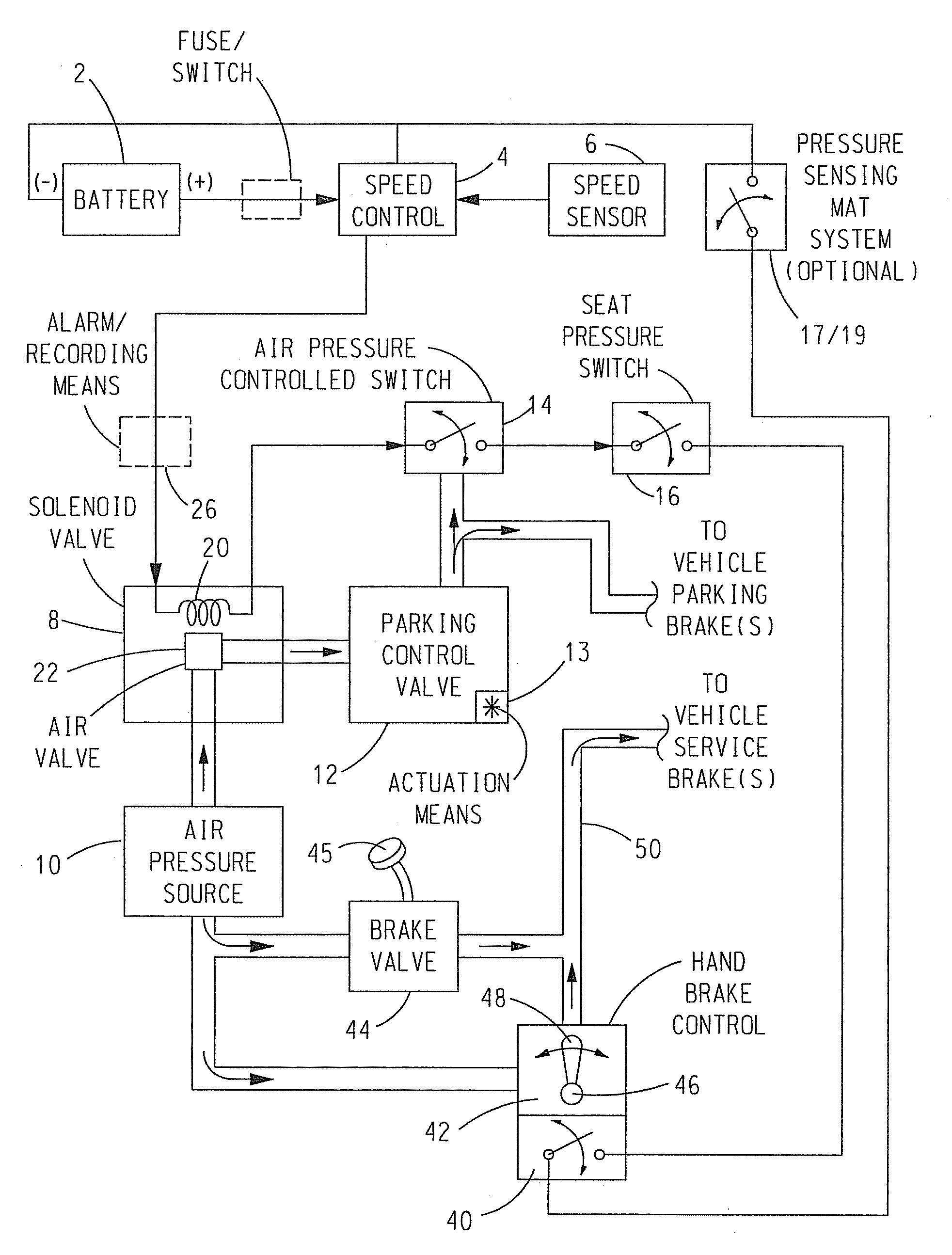
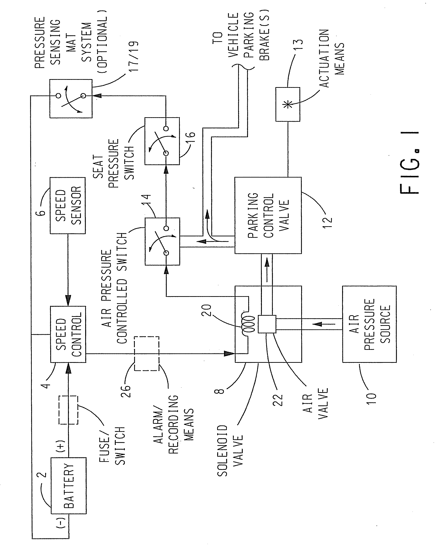
[0037]Embodiments of the invention will now be described with reference to the accompanying figures where like reference numbers correspond to like elements.

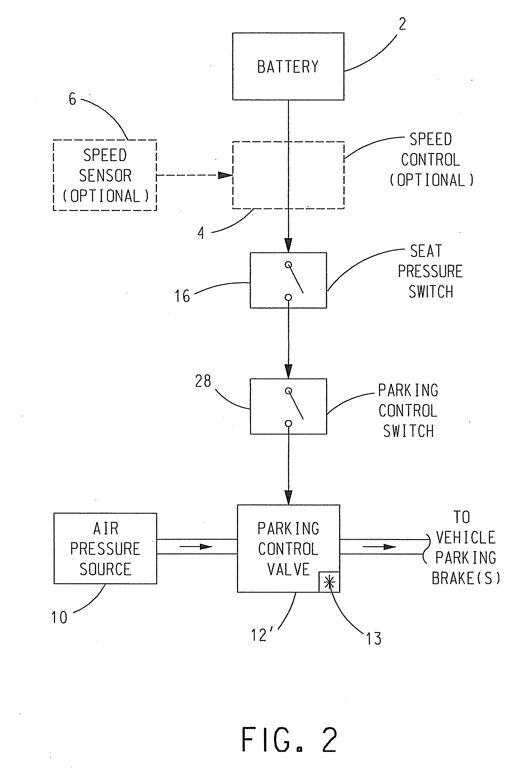
[0038]With reference to FIG. 1, one embodiment of an anti-rollaway device includes a speed control 4 having a power input coupled to the positive terminal of a battery 2 and a speed sensor input coupled to the output of a speed sensor 6.

[0039]Speed control 4 can be any suitable and / or desirable speed control. One exemplary, non-limiting example of a suitable speed control 4 is available from Hewitt Industries of 5492 Bulsa Avenue, Huntington Beach, Calif. 92649, part number 030-310 or 030-317. However, the use of this particular speed control is not to be construed as limiting the invention since it is envisioned that any other suitable and / or desirable speed control that can perform the functions of speed control 4 described hereinafter can be utilized.

[0040]Speed sensor 6 can be any suitable and / or desirable speed sensor, such...


PUM


Abstract

A vehicle anti-rollaway device includes a first switch responsive to the presence and absence of an operator at a predetermined location in the vehicle for controlling the on/off state of parking brake of the vehicle in the form of either a servo controlled parking brake or a fluid controlled parking brake. The device can also include a speed control responsive to a speed of the vehicle for controlling the on/off state of the parking brake as a function of the speed of the vehicle. The device can also include a second switch operative for controlling the response of the parking brake to the state of the first switch.

Description

CROSS-REFERENCE TO RELATED APPLICATION[0001]This application is a continuation-in-part of International Application No. PCT / US2007 / 074285, filed Jul. 25, 2007, which claims priority to U.S. Provisional Application No, 60 / 833,546, filed Jul. 26, 2006, both of which are incorporated herein by reference.BACKGROUND OF THE INVENTION[0002]1. Field of the Invention[0003]The present invention relates to preventing inadvertent rollaway of vehicles having fluid, e.g., air or hydraulic, or electrically controlled parking brake(s).[0004]2. Description of Related Art[0005]Fluid actuated parking brake(s), such as air pressure controlled parking brake(s) and hydraulic parking brake(s), or electric parking brake(s) are well-known in the art. Vehicles including such brake(s) typically include a parking control valve or servo controlled brake(s) operating under the control of an actuation means, such as a lever, knob or switch, or a switch, respectively, typically disposed inside the operator compart...

Claims


Application Information

Patent Timeline
Patent Type & Authority Applications(United States)
IPC IPC(8): F16D65/14
CPCB60T15/041B60T7/12
Inventor ACCARDI, THOMAS
Owner ACCARDI THOMAS
Why Eureka
Try Eureka