Dynamic image recording system with imaging sensors and method

Inactive Publication Date: 2009-06-25
CARL MAHR HLDG
View PDF5 Cites 11 Cited by
  • Summary
  • Abstract
  • Description
  • Claims
  • Application Information

AI Technical Summary

Benefits of technology

[0006]In a measuring system comprising an optical image recording system and a relative movement between the measured object and the image recording system, it is provided that the focal point (F) of the image recording system (3) be allowed to oscillate in scanning direction in order to generate—by superimposition of the oscillation movement of the focal point with the scanning movement—image recording intervals, duri

Problems solved by technology

In addition, it becomes unnecessary to stop the movement of the measured object or the measuring system again and again, that is, to accelerate and stop it, which woul

Method used


Image

  • Dynamic image recording system with imaging sensors and method
  • Dynamic image recording system with imaging sensors and method
  • Dynamic image recording system with imaging sensors and method

Examples


Embodiment Construction

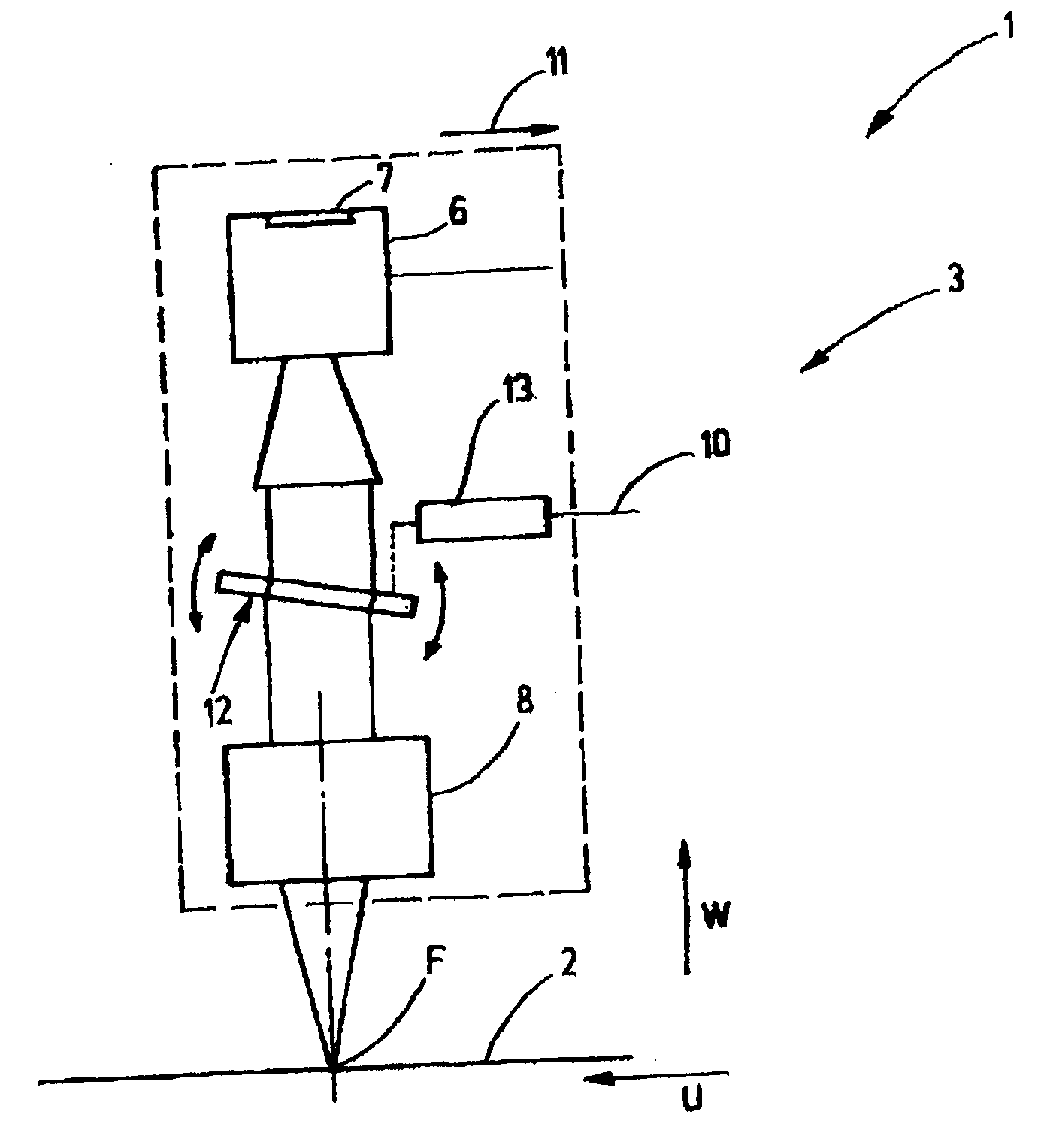
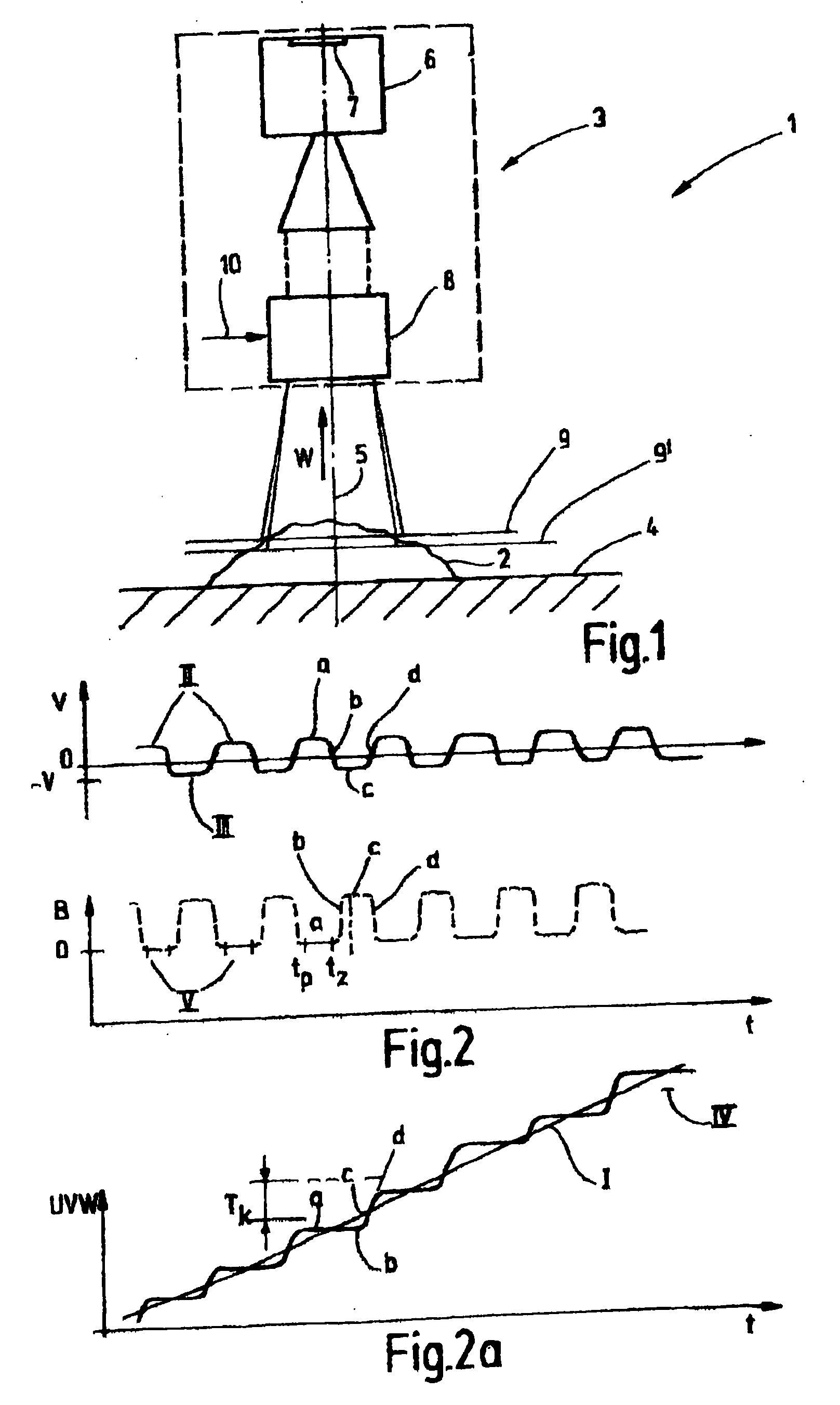
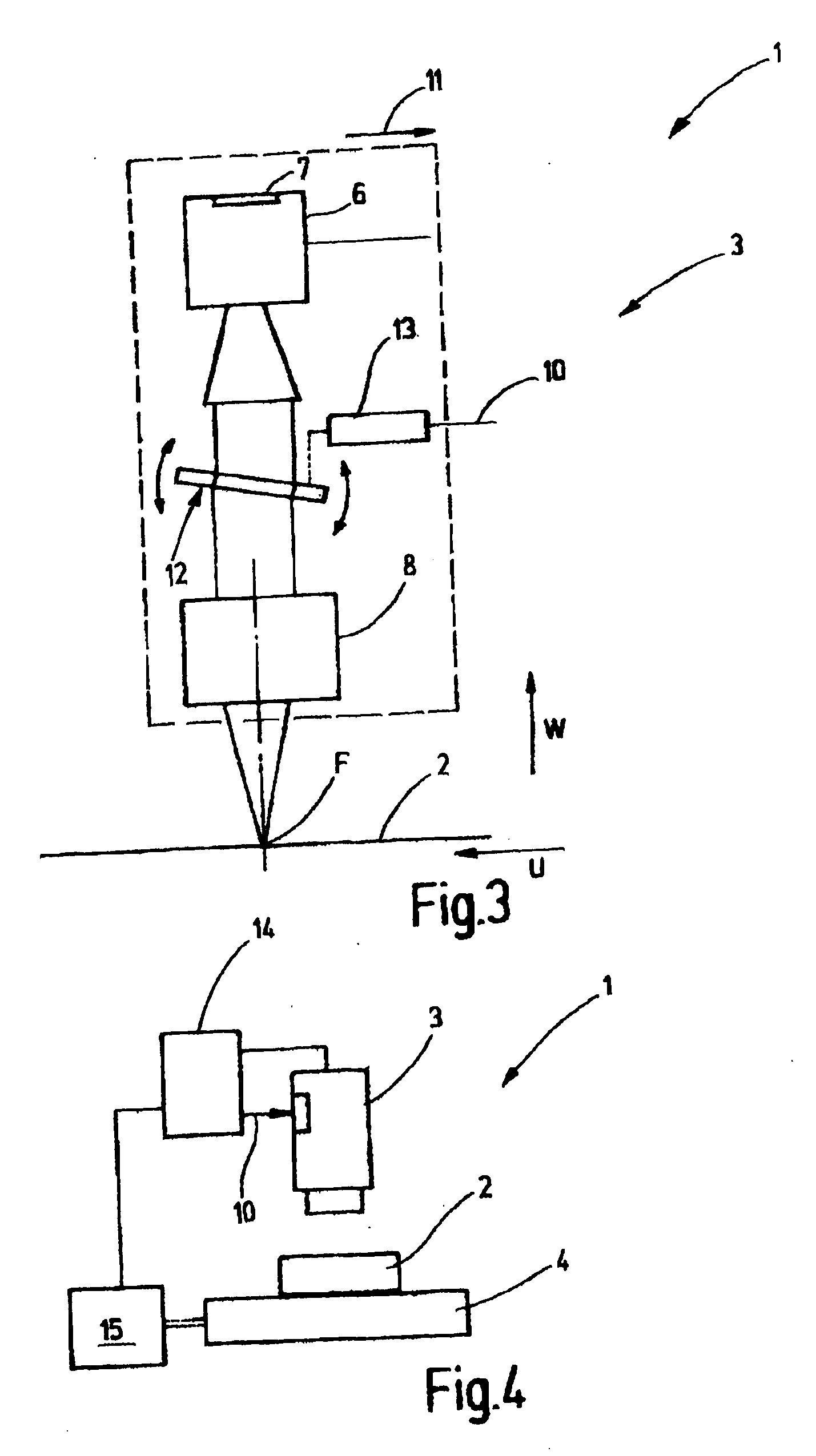
[0024]FIG. 1 shows a measuring system 1 for the optical surveying of a measured object 2. The measuring system 1 comprises an image recording system 3 and a support 4 for the measured object, these being movable relative to each other. Basically, the relative movement may comprise all three spatial directions. In the present exemplary embodiment, reference is made to the first illustration showing the relative movement along an optical axis 5, this axis coinciding with the W-direction of a camera coordinate system and being essentially perpendicular with respect to the support (4) of the measured object or the surface of the measured object 2. The UVW coordinate system of the camera head is basically independent of the XYZ coordinate system of a measuring apparatus. Still, the W-axis of the camera is occasionally referred to as the ‘Z-DirectionA’. However, the invention can be employed in particular in cases in which the movement between the object and the camera occurs in a directi...


PUM


Abstract

In a measuring system comprising an optical image recording system and a relative movement between the measured object and the image recording system, it is provided that the focal point (F) of the image recording system (3) be allowed to oscillate in scanning direction in order to generate—by superimposition of the oscillation movement of the focal point with the scanning movement—image recording intervals, during which the focal point (F) stops on the surface of the measured object (2) or, correspondingly, the image projected on the camera chip (7) stops on the camera chip. This preferably occurs during a steady unaccelerated relative movement between the measured object and the image recording system. Blurring of the edges of the images is avoided despite relatively long exposure times and moderate illumination intensities.

Description

CROSS-REFERENCE TO RELATED APPLICATION[0001]This is a continuation-in-part application of pending international application PCT / EP 2007 / 006543 filed Jul. 23, 2007 and claiming the priority of German application No. 10 2006 034 205.4 filed Jul. 25, 2006.BACKGROUND OF THE INVENTION[0002]The invention relates to a method and an apparatus for the optical surveying of a surface of a measured object by means of an image-recording system.[0003]When taking images of a measured object by means of an image recording system, in particular when surveying the object, measures preventing a blurring of the captured image must be taken. If there is a continuous motion between the measured object and the image recording system, it is possible to use flash illumination in order to produce snapshots of the object. However, already at relatively slow speeds of, for example, 10 mm / sec and exposure times of 1 / 5000 sec, it is no longer possible to perform exact measuring tasks. The relative movement for t...

Claims


Application Information

Patent Timeline
IPC IPC(8): G01C11/02
CPCG01B11/24
Inventor ZIEGENBEIN, RAINERMAHR, CARL FRIEDER
Owner CARL MAHR HLDG
Why Eureka
Try Eureka