Identification Medium

a technology of identification medium and identification plate, applied in the field of identification plate, can solve the problems of difficult identification by only using hologram, ineffective anti-counterfeiting effect, and inability to effectively obtain anti-counterfeiting effect, etc., and achieve the effect of simple structure, easy counterfeiting, and good discrimination ability

Inactive Publication Date: 2009-06-25
NHK SPRING CO LTD
View PDF7 Cites 14 Cited by
  • Summary
  • Abstract
  • Description
  • Claims
  • Application Information

AI Technical Summary

Benefits of technology

[0006]An object of the present invention is to provide a technique in which anticounterfeiting effects are better than those of discrimination techniques using the above conventional techniques, and the technique enables articles to be distinguished easily and reliably.
[0007]The present invention provides an identification medium provided with a laminated structure comprising laminated layers of a magnetically controllable layer, in which magnetic microcapsules are dispersed, and a color shifting layer. According to the present invention, the color shifting layer exhibits color shifting, and effects of the color shifting are combined with optical effects of the magnetically controllable layer. Therefore, an identification medium that is complicated and has better anticounterfeiting effects can be obtained. That is, in the present invention, an optical function of the magnetically controllable layer, in which optical characteristics are controlled by a magnetic field, is reflected in the optical characteristics of the color shifting layer, and an optical discriminating function is thereby obtained.
[0012]As black magnetic particles to be contained in microcapsules, magnetic particles formed by mixing two kinds of particles having different sizes or materials are used. In this case, when a magnetic field is applied perpendicular to the magnetically controllable layer, the magnetic particles are attracted to the surface, and the surface of the magnetically controllable layer thereby appears to be black. On the other hand, when a magnetic field is applied parallel to the magnetically controllable layer, the magnetic particles are dispersed, and the density of the powders of the pigments in the vicinity of the surface is thereby relatively increased. Therefore, the magnetically controllable layer appears to be the color of the pigments.
[0022]In the present invention, a structure is preferably formed by laminating a color shifting layer and a magnetically controllable layer in turn from an observation side. In addition, the magnetically controllable layer preferably has a structure in which one of the function of a light absorption layer and the function of a light reflection layer can be selected by applying a magnetic field. In this case, as viewed from the observation side, the back side of the color shifting layer can be magnetically changed into a light absorption layer or a light reflection layer. Accordingly, the optical function of the color shifting layer can be more complicated.
[0025]In the present invention, a magnetic layer for applying a magnetic field to the magnetically controllable layer is preferably provided to the laminated structure. In this case, whereas a magnetic field is not applied from the outside, a magnetic field is continuously applied to the magnetically controllable layer, and the optical function of the magnetically controllable layer, which may occur by applying a magnetic field, can thereby be obtained. By applying a magnetic field, which is stronger than that generated by the magnetic layer, from the outside, the optical function of the magnetically controllable layer can be controlled. As a method for forming a magnetic field, a method in which a laminated structure including a magnetic material is subjected to a strong magnetic field so as to magnetize it may be mentioned.
[0026]According to the present invention, an identification medium having a simple structure can be obtained, and the identification medium will provide a good discriminating ability and cannot be easily counterfeited.

Problems solved by technology

Counterfeits of articles (for example, merchandise and garments), which are produced by copying the appearances of authentic articles, are being sold, and this cause problems.
However, it is relatively easy to obtain inks similar to various special inks, and anticounterfeiting effects cannot be effectively obtained.
Visual holograms, which are sophisticated counterfeits, are on the market, and the authenticity thereof is not easily determined by observation.
Therefore, determination of the authenticity by only using a hologram is difficult.

Method used


Image

  • Identification Medium
  • Identification Medium
  • Identification Medium

Examples


first embodiment

1. First Embodiment

Structure

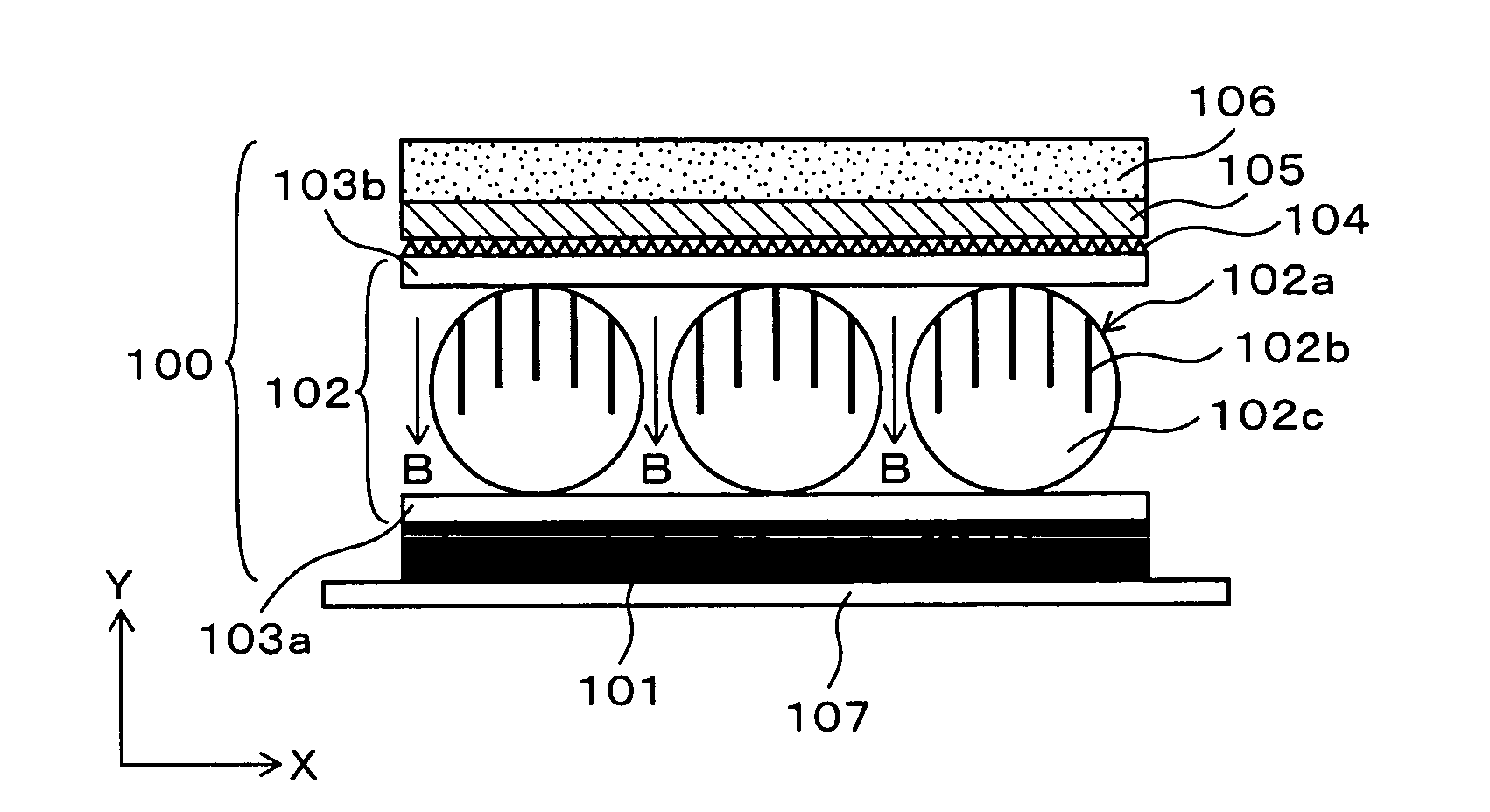
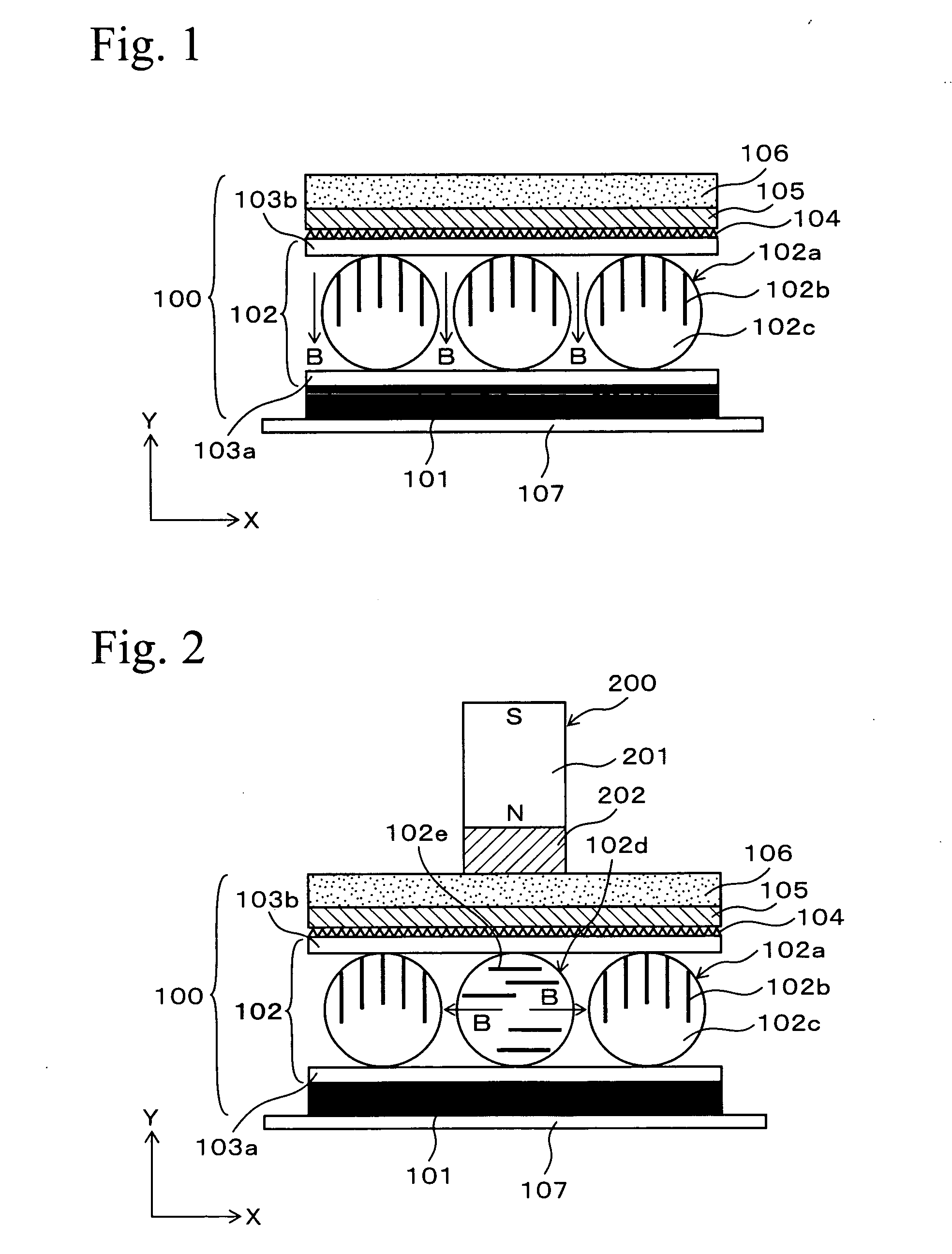
[0037]FIG. 1 is a cross sectional drawing schematically showing an outline of an identification medium of the first embodiment. FIG. 1 shows an identification medium 100 comprising a magnetically controllable sheet 102, in which magnetic microcapsules 102a are dispersed and maintained, on a light absorption layer and concurrently adhesive layer 101. Moreover, the identification medium 100 comprises a cholesteric liquid crystal layer 105 on the magnetically controllable sheet 102. The light absorption layer and concurrently adhesive layer 101 is a layer that is made of an adhesive material with a black pigment (or a black dye) added thereto, and it is used for affixing the identification medium 100 on an article to be identified. The light absorption layer and concurrently adhesive layer 101 absorbs light that is transmitted through the cholesteric liquid crystal layer 105 and is attached with a separator 107. In order to affix the identification medium 10...

second embodiment

2. Second Embodiment

[0062]In the first embodiment, the magnetically controllable sheet 102 needs not be provided over the entire surface and may be provided partially. For example, the magnetic microcapsules 102a are dispersed in an area so as to form a pattern of a character. In this case, an area other than the area in which the magnetic microcapsules 102a are dispersed is filled with a light transparent material, so that light transmitted through the area is absorbed by the light absorption layer and concurrently adhesive layer 101.

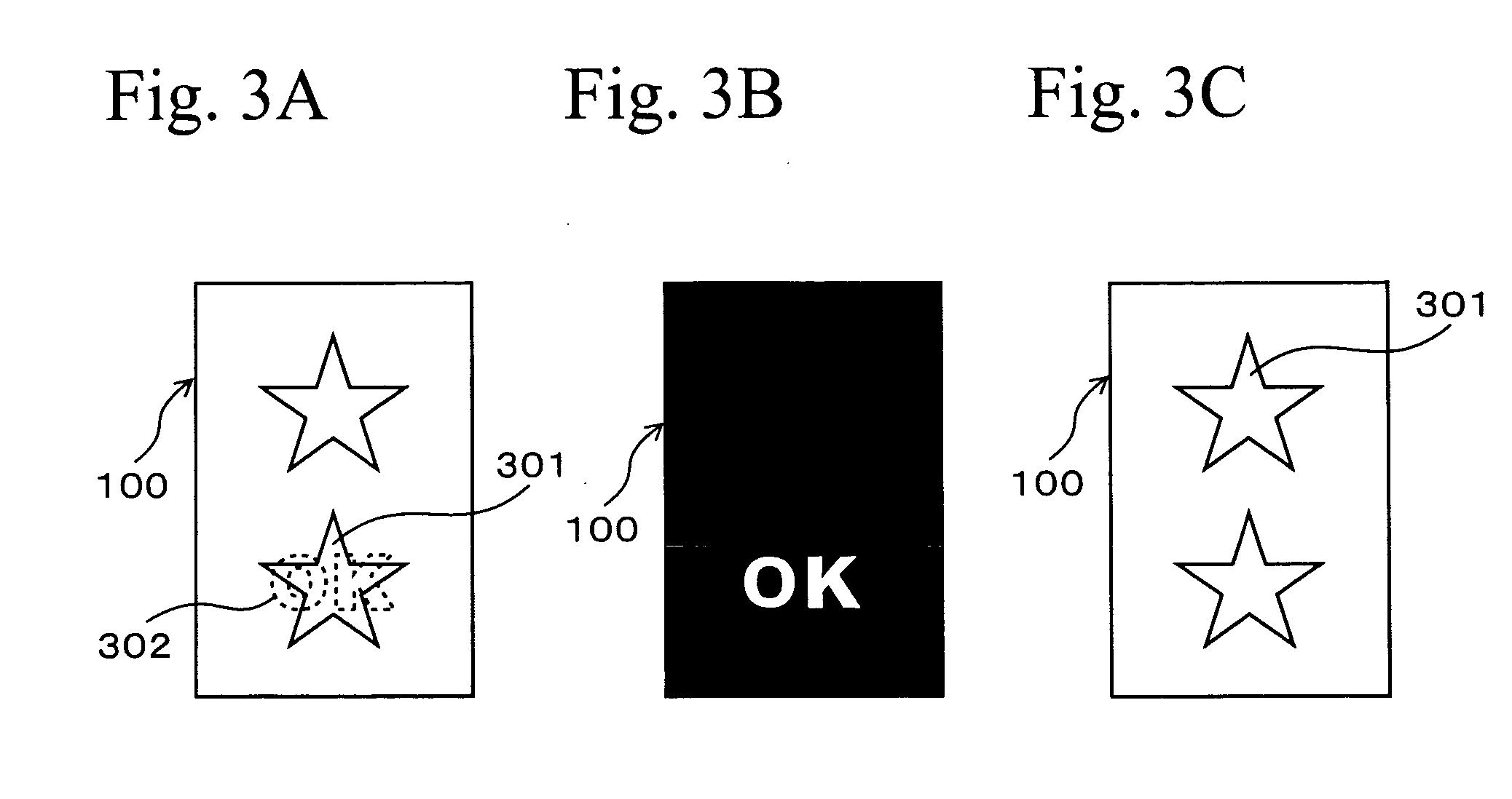
[0063]FIGS. 3A to 3C are schematic views showing appearances of a discrimination medium 100 when the magnetic microcapsules 102a are dispersed in an area so as to form a pattern of a character. In this case, an example will be described, and in the example, the magnetic microcapsules 102a are dispersed in an area so as to form a character pattern of “OK”, and an embossed pattern 104 forms a star-shaped hologram figure.

[0064]First, a parallel magnetic f...

third embodiment

3. Third Embodiment

[0068]In the first embodiment, spherical black magnetic particles, powder of white pigments, and dispersing liquid are contained into the magnetic microcapsules 102a. FIGS. 4A to 4C are schematic views showing a cross sectional structure of an identification medium in the third embodiment. FIG. 4A shows a condition in which no magnetic field is applied, FIG. 4B shows a condition in which a magnetic field is applied to the entire back surface, and FIG. 4C shows a condition in which a magnetic field is partially applied from the surface side. As shown in FIG. 4A, the identification medium 100 of this embodiment comprises magnetic microcapsules 402a that are changed from the magnetic microcapsules 102a shown in FIG. 1. In this case, the portions having the same reference numerals as those in FIG. 1 have the same structures as those shown in FIG. 1.

[0069]The magnetic microcapsules 402a has a structure containing black magnetic particles 402b, nonmagnetic powder of whi...


PUM

PropertyMeasurementUnit
thicknessaaaaaaaaaa
mean diameteraaaaaaaaaa

Abstract

An identification medium provided with a laminated structure comprises laminated layers of a magnetically controllable layer, in which magnetic microcapsules are dispersed, and a color shifting layer.

Description

TECHNICAL FIELD[0001]The present invention relates to a technique for determining whether or not articles are authentic by using visual effects. In particular, the present invention relates to a technique using specific views obtained by viewing angles and specific polarization filters, and optical characteristics vary depending on the presence of a magnetic field, in combination therewith.BACKGROUND ART[0002]Counterfeits of articles (for example, merchandise and garments), which are produced by copying the appearances of authentic articles, are being sold, and this cause problems. Under these circumstances, in order to ensure performance, reliability, and security of articles, and to maintain the value of the brands of articles, techniques for verifying authenticity of articles are required. As a technique for verifying the authenticity of the articles, a method of printing on articles with a special ink, and a method of affixing a chip having special optical reflection characteris...

Claims


Application Information

Patent Timeline
Patent Type & Authority Applications(United States)
IPC IPC(8): G02F1/17B32B7/02G02F1/19B42D15/10G03H1/18G02F1/16757G02F1/1677
CPCB42D2033/16Y10T428/24802B42D2035/24B42D2035/34G02F1/167G02F2001/094G02F2001/1672G03H1/02G03H1/0244G03H1/0256G03H2001/0016G03H2250/33G03H2250/38G03H2250/41Y10S428/90Y10S428/916B42D25/29B42D25/328Y10T428/24901Y10T428/24893Y10T428/32Y10T428/24942B42D2033/26G03H1/0011G03H2250/14G02F1/1681Y10T428/249994Y10T428/249995Y10T428/249997G02F1/1677G02F1/16757G02F1/094B42D25/364B42D25/369
Inventor TAKEUCHI, ITSUOHOSHINO, HIDEKAZUNASUBIDA, SHINYA
Owner NHK SPRING CO LTD
Why Eureka
Try Eureka