

Gas-liquid separator for fuel cell system
- Summary
- Abstract
- Description
- Claims
- Application Information
AI Technical Summary
Benefits of technology
Problems solved by technology
Method used
Image

Examples
first embodiment
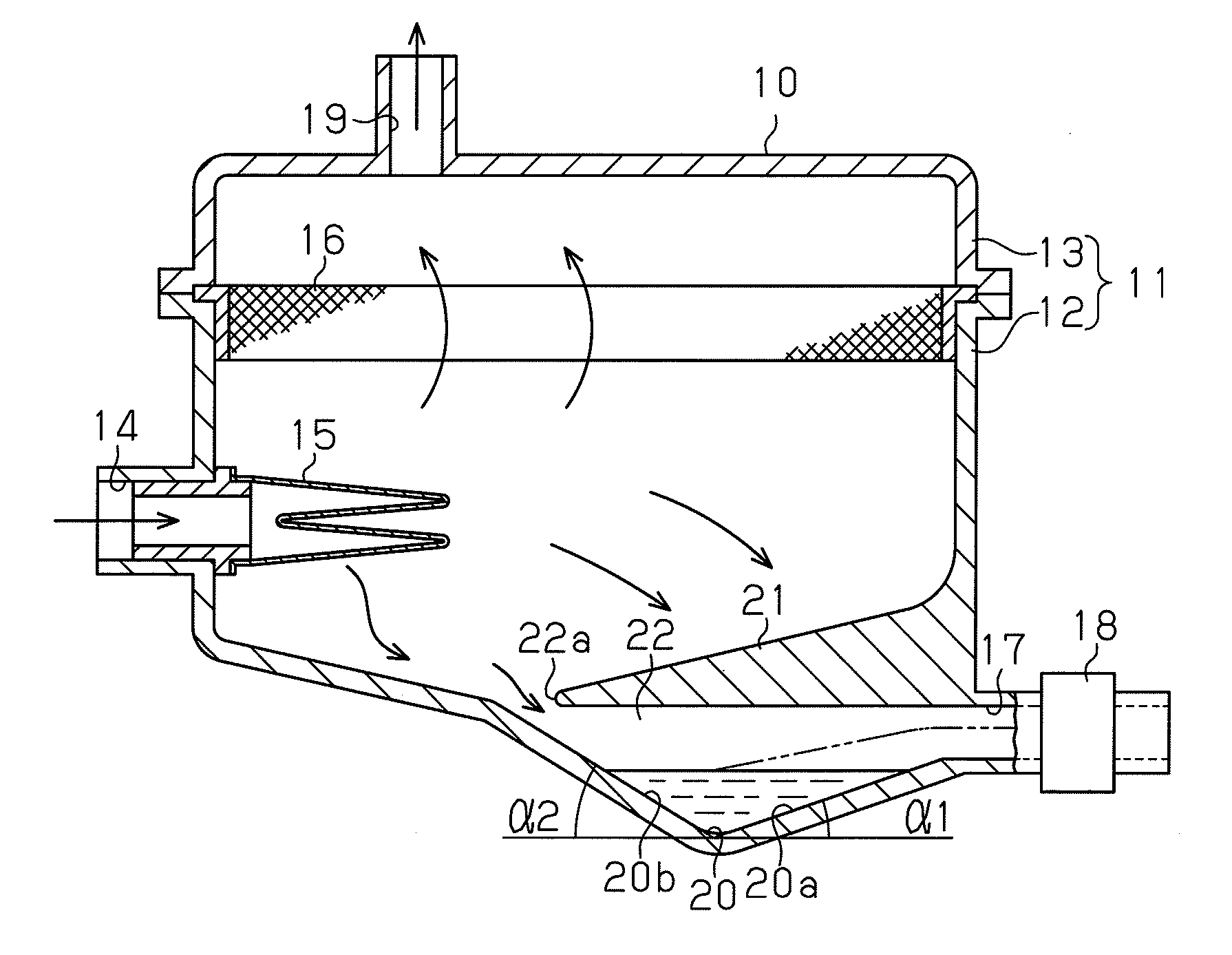
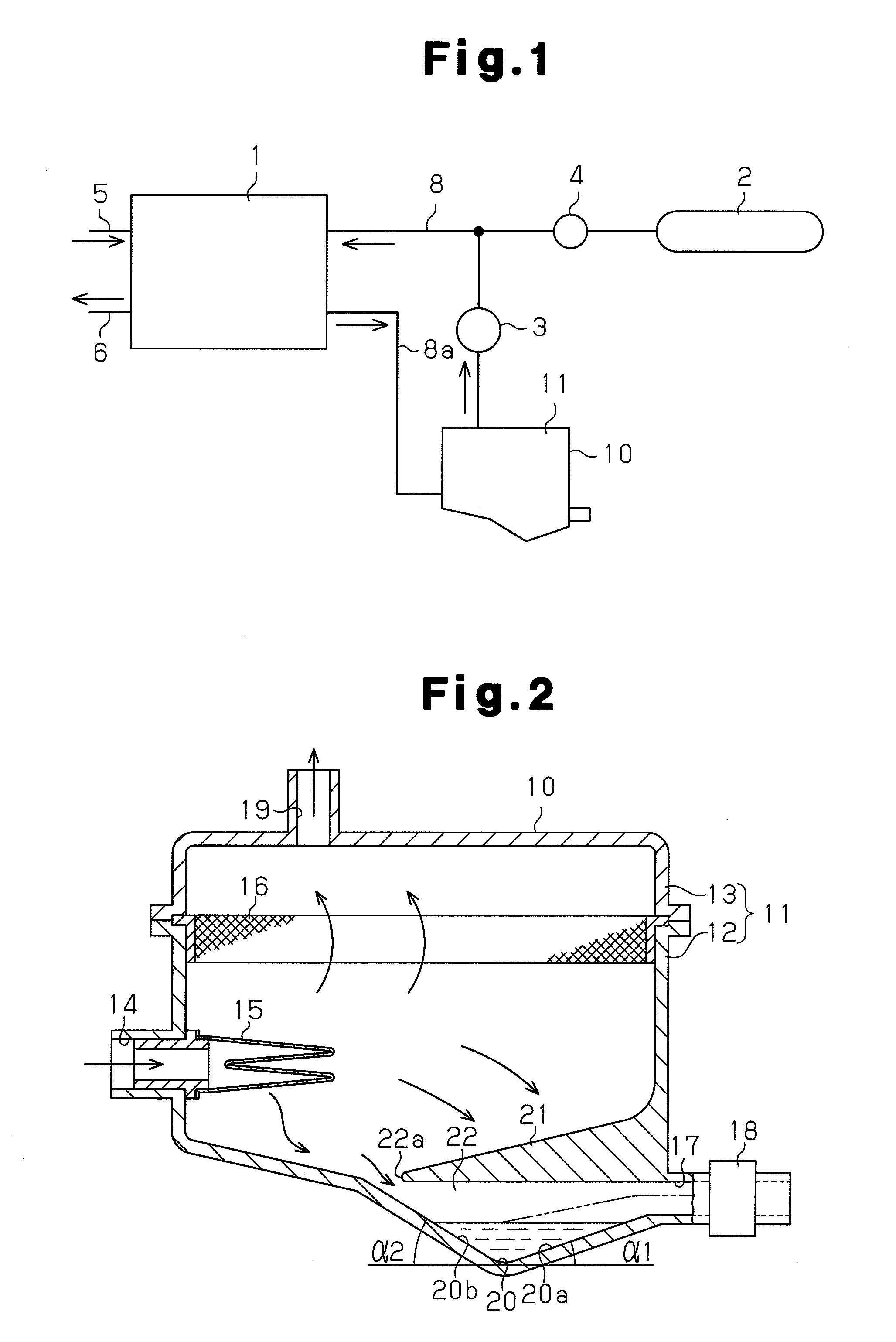
[0018]the present invention will now be described with reference to FIGS. 1 and 2.
[0019]First, a fuel cell system will be roughly described with reference to FIG. 1. A cell stack 1 includes a plurality of single cells (not shown) and performs cell reaction. An air supply passage 5 is connected to the cell stack 1 to supply air, which is oxidation gas. Also, an air discharge passage 6 is connected to the cell stack 1 to discharge air and product water from the cell stack 1. A hydrogen discharge portion (not shown) and a hydrogen introduction portion (not shown) of the cell stack 1 are connected to one end and the other end of a circulation path 8a forming a hydrogen circuit 8, respectively.
[0020]Of unreacted excess hydrogen (gas) and product water discharged from the cell stack 1, the circulation path8a circulates the hydrogen and supplies the hydrogen, together with new hydrogen, to the cell stack 1. The circulation path 8a discharges the product water to the outside. A circulation ...
second embodiment
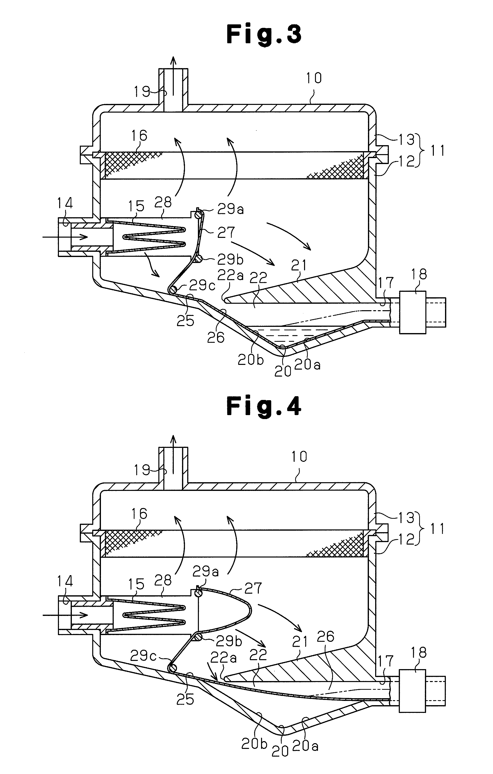
[0039]In the second embodiment, a forcing mechanism 25 is provided at the bottom of the water retaining portion 20 as shown in FIGS. 3 and 4. That is, a water impermeable sheet 26 is laid on the inner bottom surface of the water retaining portion 20. In the lower case member 12, an air impermeable pressure receiving ribbon 27 is provided at the downstream side of the filter 15. The pressure receiving ribbon 27 is supported with a support frame 28 and guide rollers 29a, 29b, 29c. One end of the pressure receiving ribbon 27 is integrally connected to the sheet 26.
[0040]When the discharge valve 18 is closed, that is, when hydrogen is not being spurted through the inlet 14, the sheet 26 is laid on and conforms to the shape of the bottom surface of the water retaining portion 20 due to the own weight as shown in FIG. 3. Thus, product water that drips from the ion-exchange resin 16 and the inner wall of the case 11 is retained on the sheet 26 in the water retaining portion 20. In contrast...
third embodiment
[0044]the present invention will now be described.
[0045]According to the third embodiment, a drain port 31, which serves as a drain portion, is provided at the bottom of the water retaining portion 20. An electromagnetic drain valve 32 is located in the drain port 31. When the fuel cell system is stopped, the drain valve 32 is opened, so that product water in the water retaining portion 20 is discharged to the outside through the drain port 31 and the water retaining portion 20 is emptied.
[0046]The third embodiment provides the same advantages as the advantages (1) and (3) of the first embodiment.
[0047]In addition, the third embodiment provides the following advantage.
[0048](5) Since the product water in the water retaining portion 20 is moved downward and discharged, the water retaining portion 20 is more reliably emptied.
[0049]The present invention is not limited to the above illustrated embodiments, but may be modified as follows.
[0050]As shown in FIG. 6, the opening 22a of the g...
PUM
 Abstract
Description
Claims
Application Information