Method of measuring flow sections of a turbomachine nozzle sector by digitizing

a technology of turbomachine nozzles and flow sections, applied in the direction of engine fuction, analog and hybrid computing, analogue computers, etc., can solve the problems of poor accuracy, lack of accuracy, and inability to obtain information about the sector other than its flow sections, etc., and achieves only a relatively small number of data points concerning the par

Inactive Publication Date: 2009-06-25
SNECMA SERVICES
View PDF21 Cites 11 Cited by
  • Summary
  • Abstract
  • Description
  • Claims
  • Application Information

AI Technical Summary

Benefits of technology

[0025]The term “digitizing” is used herein to mean any method of obtaining three-dimensional coordinates on the part, whether using mechanical means with a feeler tip or optical means using a laser scanner or structured light projection, for example, or indeed by photogrammetry. In any event, digitizing assumes that a large number of thr

Problems solved by technology

The measurement method as defined in this way suffers from the drawback of poor accuracy and of not enabling information to be obtained about the sectors other than their flow sections.
Although it is relatively simple to implement, it suffers from v

Method used


Image

  • Method of measuring flow sections of a turbomachine nozzle sector by digitizing
  • Method of measuring flow sections of a turbomachine nozzle sector by digitizing
  • Method of measuring flow sections of a turbomachine nozzle sector by digitizing

Examples


Embodiment Construction

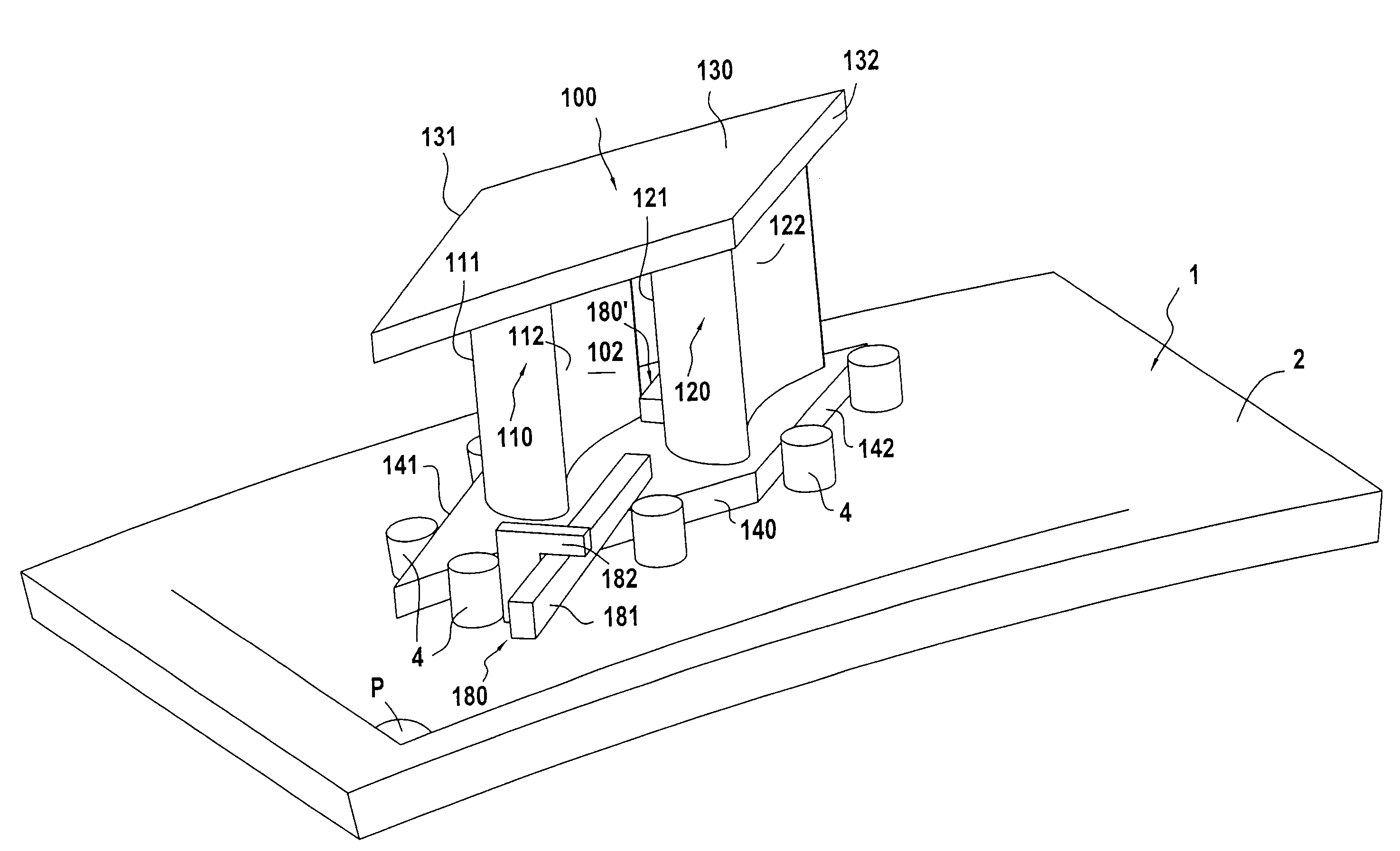
[0065]A nozzle sector, referred to as a “measured” sector in which it is desired to measure the flow sections, is described below with reference to FIGS. 1 to 3. Combining such sectors enables a nozzle to be built up, arranged around a nozzle axis.

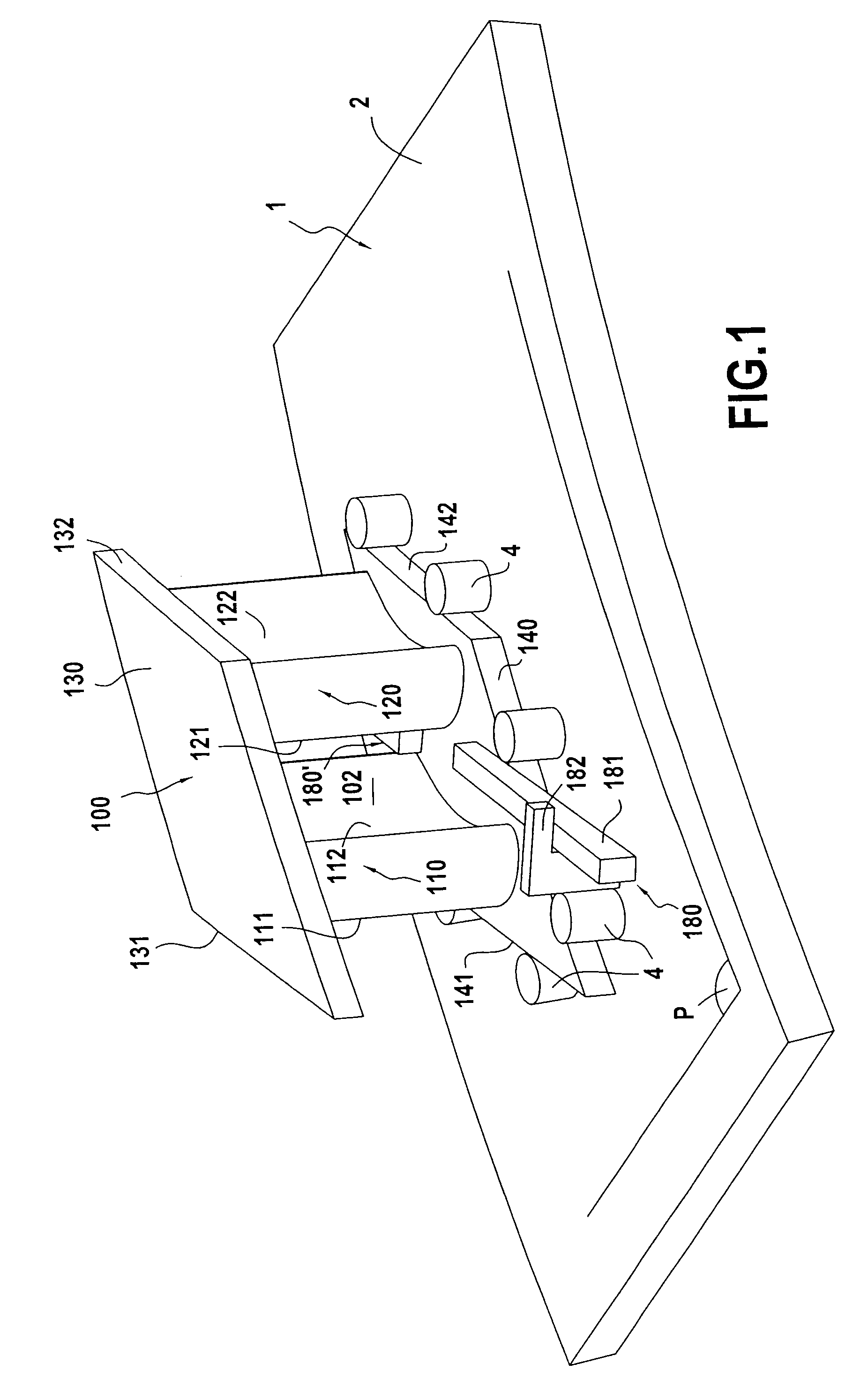
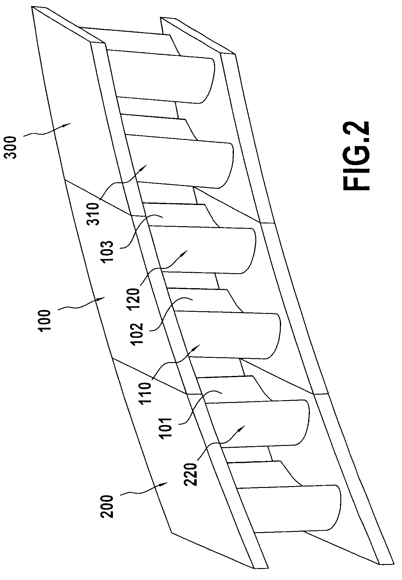
[0066]The nozzle sector 100 in FIG. 1 comprises two substantially parallel platforms 130 and 140. These platforms are substantially cylindrical in shape about the axis of the nozzle. These platforms 130, 140 have contact surfaces 131, 132, 141, 142 directed respectively towards the two nozzle sectors located on either side of the measured sector 100 (in the assembly relative position). The contact surfaces 131, 132, 141, 142 are designed to keep adjacent nozzle sectors in a contacting relative position, e.g. the sectors 100, 200, and 300 visible in FIG. 2.

[0067]The nozzle sector 100 also has two vanes 110, 120. Each of the vanes presents an airfoil with a suction side 111, 121 and a pressure side 112, 122. Since there are only two vanes in...


PUM


Abstract

A method of measuring flow sections of a turbomachine nozzle sector relative to two reference vanes, wherein:
a) a three-dimensional numerical model of the sector is produced by digitizing;
b) numerical models are provided for the two reference vanes;
c) the reference vanes are reset at the ends of the numerical model of the sector in their assembly relative positions in the nozzle; and
d) the flow sections of the sector are determined from sections of the numerical models of the sector and of the reference vanes;
the nozzle sector having contact surfaces, and being positioned relative to adjacent nozzle sectors by putting said contact surfaces into abutment, the numerical models of the sector and of the reference vanes including models of the contact surfaces involved in putting them into their assembly relative position, and step c) being performed by putting the contact surfaces into correspondence.

Description

FIELD OF THE INVENTION[0001]The present invention relates to a method of measuring flow sections of a turbomachine nozzle sector. More generally, the invention relates to a method of selecting an arrangement of sectors for a turbomachine nozzle.BACKGROUND OF THE INVENTION[0002]In a turbomachine nozzle, a sector is a known part that comprises one or more vanes interconnecting two platforms. The nozzle is essentially constituted by uniting sectors in a ring. In the nozzle, each sector is positioned in or takes up an assembly position relative to two adjacent sectors situated on either side thereof by means of contact surfaces of its platforms coming into abutment with contact surfaces of the platforms of the adjacent sectors.[0003]The flow sections of a sector are the areas, measured perpendicularly to the stream flow direction, of the sections occupied by the stream(s) passing through the nozzle sector. By extension, the term “flow section” may also designate merely the width of the ...

Claims


Application Information

Patent Timeline
IPC IPC(8): G06G7/64
CPCF01D5/141F05D2250/74F05D2260/12F05D2250/20F05D2230/60F05D2230/80F05D2240/12G01B21/28
Inventor MENUEY, JUSTINE
Owner SNECMA SERVICES
Why Eureka
Try Eureka