Method and system for integrating ultrasound inspection (UT) with a coordinate measuring machine (CMM)

a technology of coordinate measuring machine and ultrasound, which is applied in the field of assembling a measurement probe, can solve the problems of inability to fully realize the setup and inspection process, inconvenient use, and inability to meet the requirements of in-situ inspection,

Inactive Publication Date: 2009-07-02
GENERAL ELECTRIC CO
View PDF23 Cites 73 Cited by
  • Summary
  • Abstract
  • Description
  • Claims
  • Application Information

AI Technical Summary

Problems solved by technology

Accordingly, a significant amount of time may be required to complete the setup and inspection process for each individual process of CT, CMM, and UT.
Accordingly, known methods are generally time-consuming, not suitable for in-situ inspection, and/or expensive.
Further,

Method used


Image

  • Method and system for integrating ultrasound inspection (UT) with a coordinate measuring machine (CMM)
  • Method and system for integrating ultrasound inspection (UT) with a coordinate measuring machine (CMM)
  • Method and system for integrating ultrasound inspection (UT) with a coordinate measuring machine (CMM)

Examples


Embodiment Construction

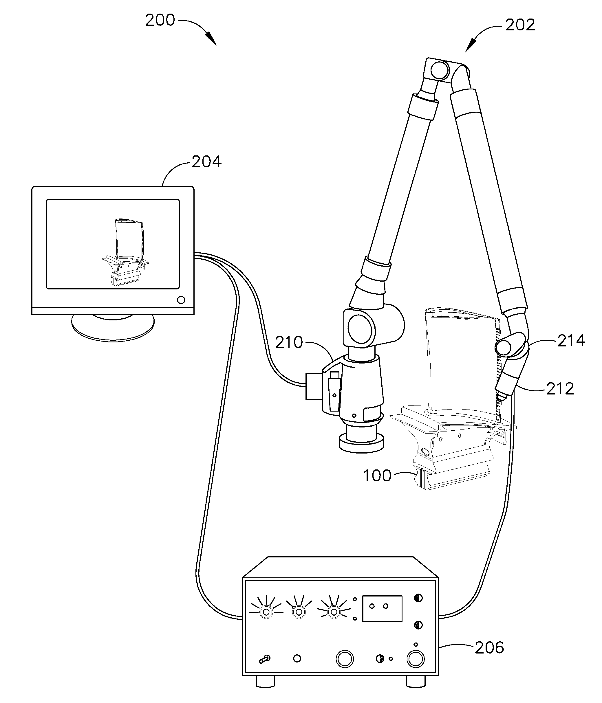
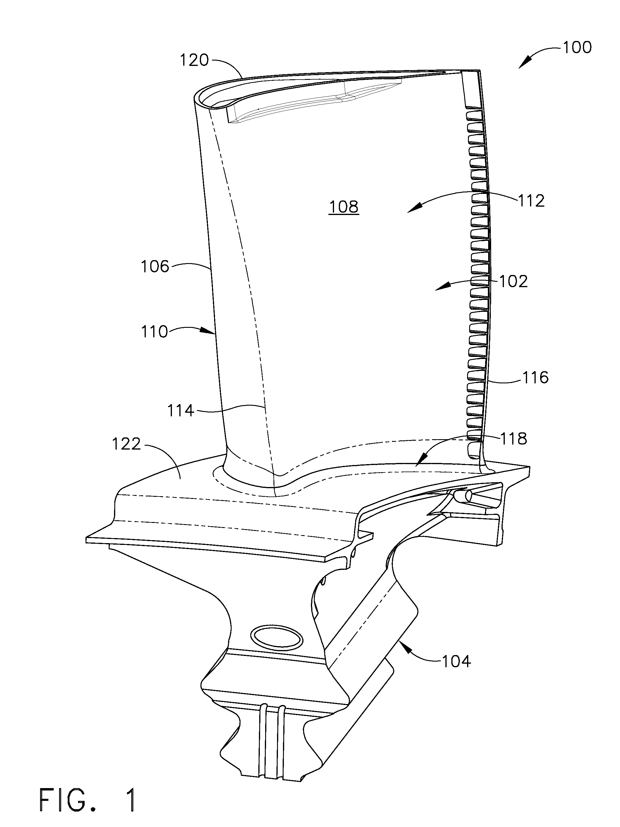
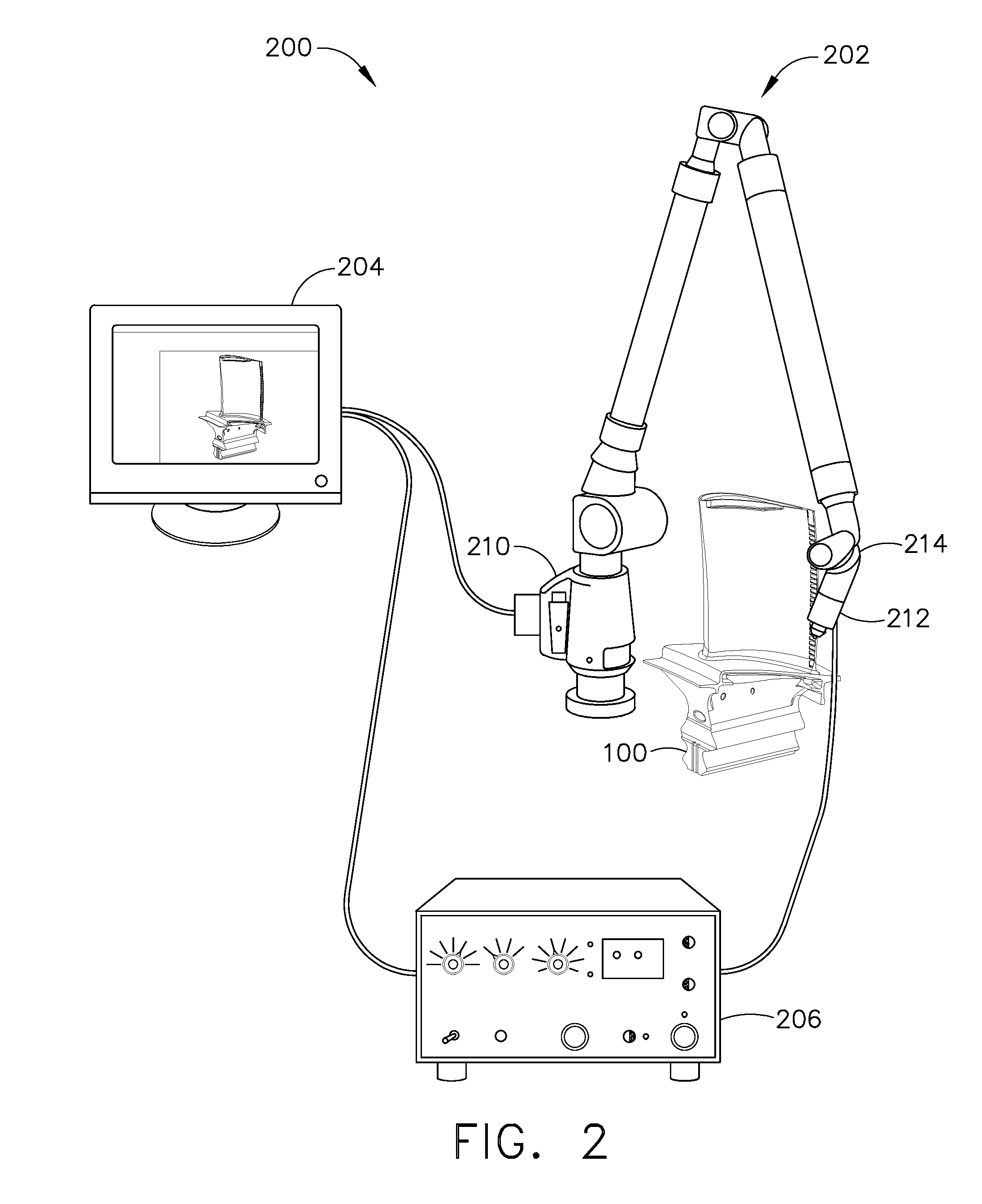
[0010]An exemplary embodiment of the invention provides a system for measuring a machine component, such as, but not limited to, a blade. The system includes a measurement probe for measuring the machine component and a display for displaying measurements of the machine component. The measurement probe includes a coordinate measuring machine (CMM) probe coupled to an ultrasonic probe. The ultrasonic probe measures a position of at least one internal defect, such as a crack, within the machine component and represents a position of each internal defect with coordinates determined by the CMM probe. In another embodiment, the measurement probe may be a customized inspection probe that includes an ultrasonic probe installed on a CMM machine and having both ultrasonic capabilities and CMM capabilities. In such an embodiment, the ultrasonic probe is not physically coupled to the CMM probe. In any embodiment, the measurement probe combines the capabilities of ultrasonic inspection and CMM ...


PUM


Abstract

A method is provided for assembling a measurement device for use in measuring a machine component. The method includes providing a coordinate measuring machine (CMM). The method also includes combining ultrasonic inspection (UT) capabilities and CMM capabilities to form an inspection probe. The inspection probe is installed on the CMM so that the inspection probe measures external boundaries of the machine component with the CMM capabilities and substantially simultaneously measures internal boundaries of the machine component with the UT capabilities.

Description

BACKGROUND OF THE INVENTION[0001]The field of the present invention relates generally to measurement probes, and more specifically, to a method of assembling a measurement probe for use in measuring a machine component.[0002]Prior to being placed in service, at least some known rotor blades or other parts with internal geometry or with narrow openings are measured using measurement probes to ensure that that the blade has the proper dimensions for use in a turbine engine. Often, known blades are inspected via a non-destructive inspection technique to ensure that each blade does not include internal defects and / or cracks that are not visible to the naked eye. Accordingly, it is generally important to measure both the external and internal geometry of the blade.[0003]Known methods for measuring a blade require two separate processes to inspect both the internal and external geometry of the blade. First, at least some known blades are inspected using one of computed tomography (CT) and...

Claims


Application Information

Patent Timeline
IPC IPC(8): G01N29/265G01B5/012
CPCG01B5/012G01B17/02G01B21/04G01B21/047Y10T29/49826G01N2291/02854G01N2291/044G01N2291/2693G01N29/265
Inventor LITTLE, FRANCIS HOWARD
Owner GENERAL ELECTRIC CO
Why Eureka
Try Eureka