
Collapsible Solar System

a solar panel and solar panel technology, applied in the field of solar panels, can solve the problems of complex structure and relatively high installation cost of solar panels, and achieve the effect of double the gain of the tracking system and excellent tracking accuracy of the present invention

Inactive Publication Date: 2009-07-02
GUNN JR ROSS +1
View PDF6 Cites 78 Cited by
  • Summary
  • Abstract
  • Description
  • Claims
  • Application Information

AI Technical Summary

Benefits of technology

[0012]The second objective of the present invention is to provide a collapsible solar system, wherein the solar panel can be completely folded flat on the roof of the recreational vehicle during traveling.
[0014]The fourth objective of the present invention is to provide a collapsible solar system, wherein tile solar panel is automatically moved to track the direction of the sun via a fight sensing unit so that the solar panel moves horizontally and vertically as the sun “moves”. In particularly, the light sensing unit comprises two light sensors for the vertical tracking axis and another two light sensors for the horizontal tracking aids. Each of the light sensors is mounted within a housing with an aperture that allows sunlight to fall on half of each light sensor when the sensor is “on axis” with the sun. By using the two light sensors per axis, the tracking system gain is doubled over the conventional sensor. Therefore, the tracking accuracy of the present invention is extremely good (typically a fraction of a degree).

Problems solved by technology

However, as it is mentioned above, the solar panel is stationary so that the solar panel cannot be moved towards the sun as the sun “moves”.
However, such folding frame requires a complicated structure and the installation cost of the solar panel is relatively high.

Method used


Image

  • Collapsible Solar System
  • Collapsible Solar System
  • Collapsible Solar System

Examples


Embodiment Construction

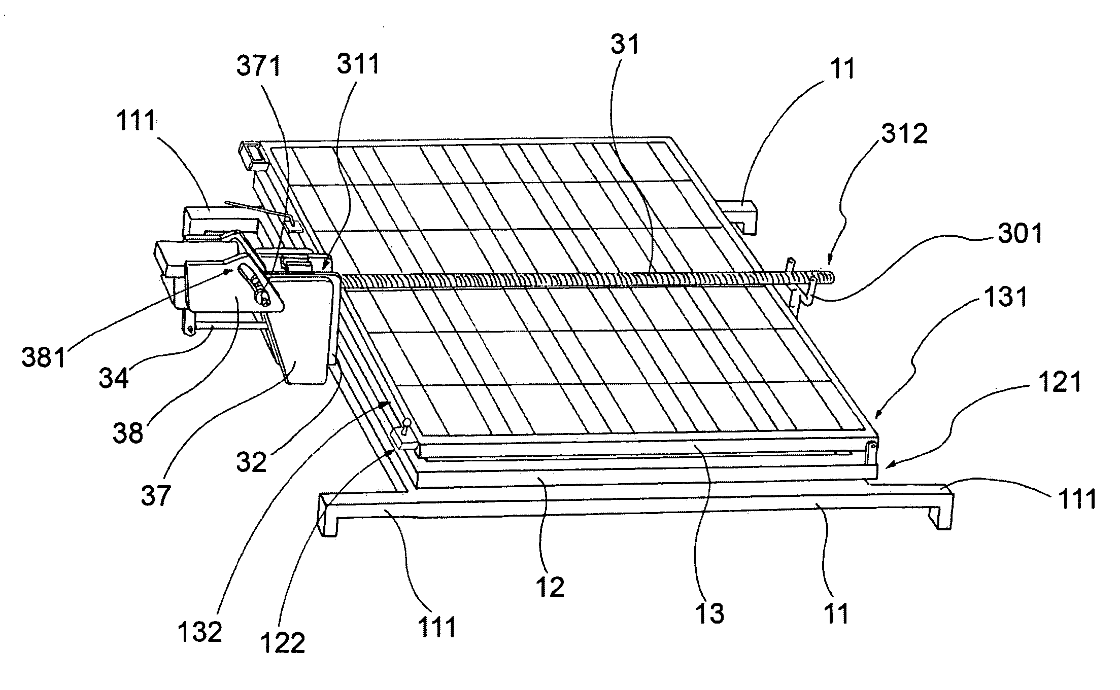
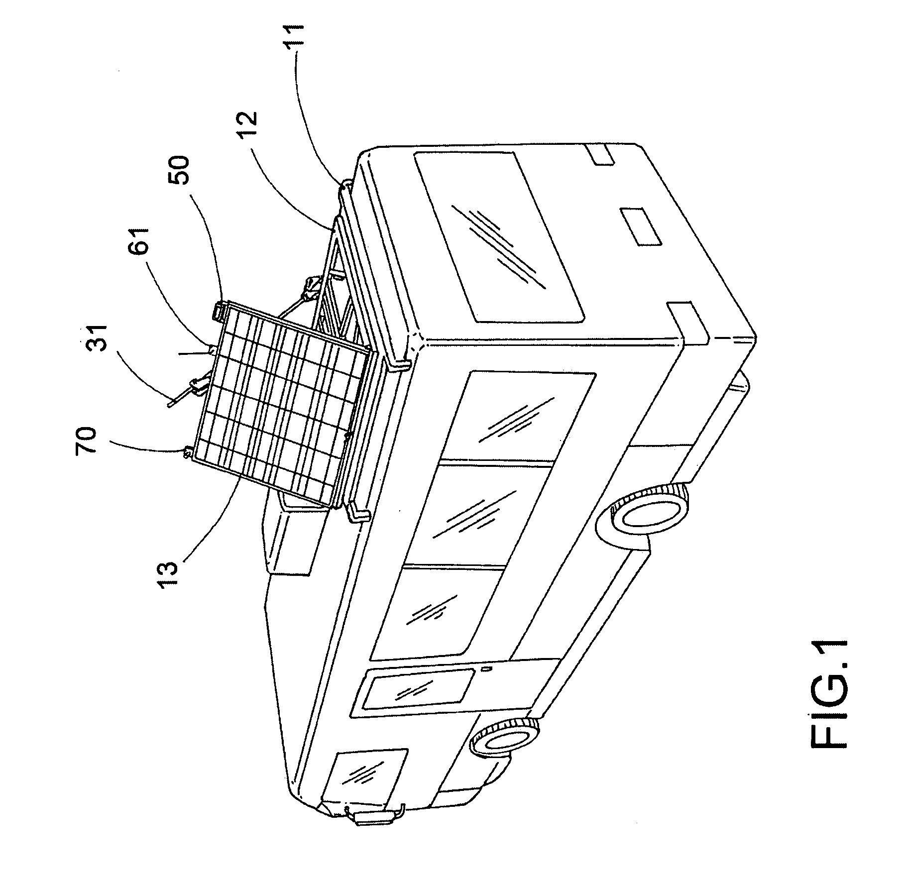
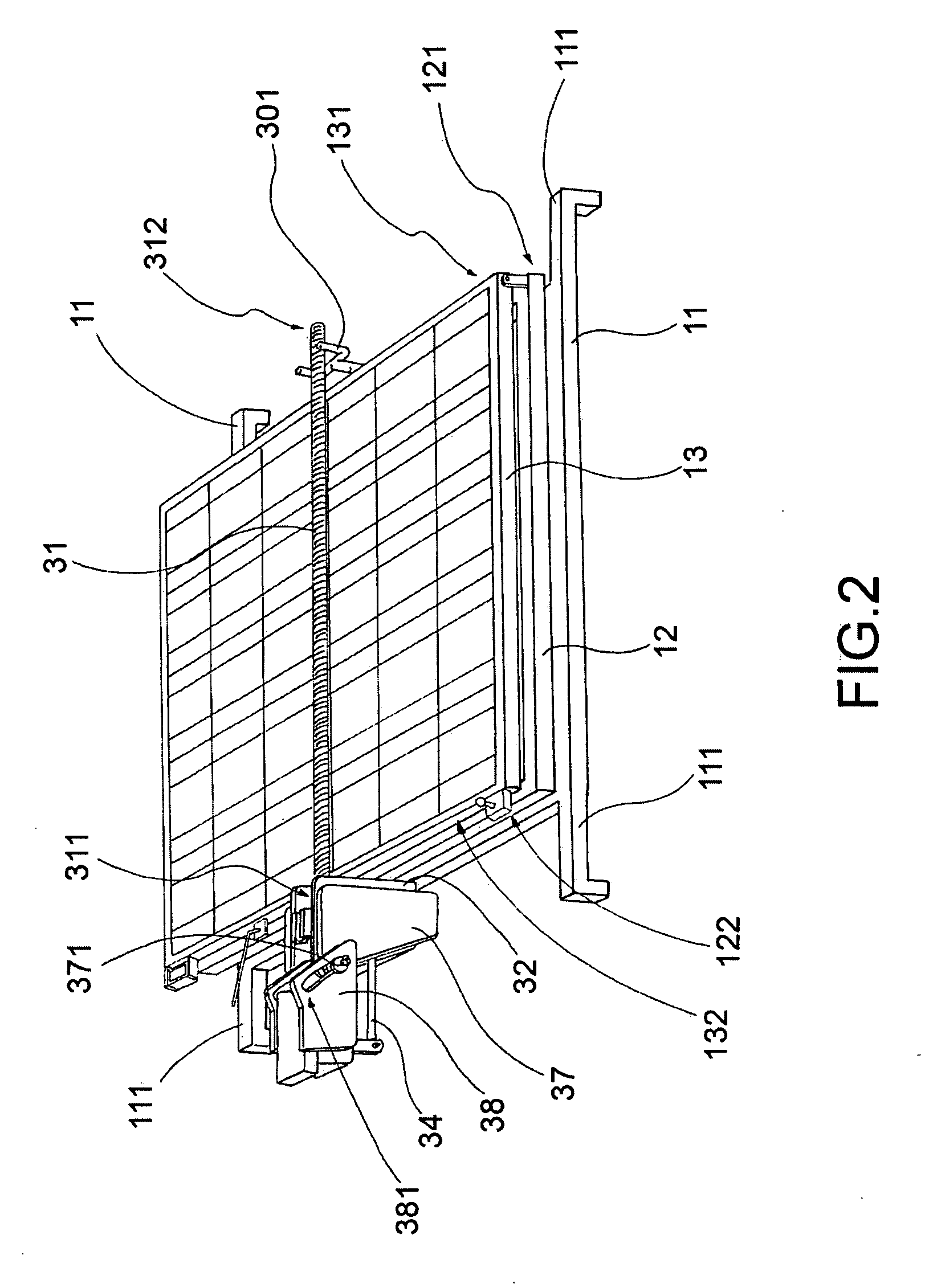
[0030]Referring to FIGS. 1 and 2, a collapsible solar system in accordance with the present invention is illustrated, wherein the collapsible solar system of the present invention is adapted for mounting on a platform collect solar energy at anytime. For simple representation and easy understanding, the collapsible solar system of the present invention is mounted on a roof of a recreational vehicle as an example. The collapsible solar system comprises a frame structure and a sunlight tracking arrangement.

[0031]As shown in FIG. 2, the frame structure comprises a supporting base 11 adapted for mounting on a roof of the recreational vehicle and a rotational frame 12 supported on the supporting base 11, wherein the rotational frame 12 has a first edge 121 and an opposed second edge 122. The frame structure further comprises a solar panel 13 having a pivot edge 131 pivotally coupling with the first edge 121 of the rotational frame 12 and an opposed controlling edge 132, wherein the solar...


PUM


Abstract

A collapsible solar system includes a frame structure and a sunlight tracking arrangement. The frame structure includes a supporting base adapted for mounting on a platform and a solar panel pivotally coupling with a rotational frame which is rotatably supported on the supporting base. The solar panel is pivotally folded between a stored position that the solar panel is laid flat on the platform, and a tracking position that the solar panel is pivotally folded at an inclination angle to be perpendicular to the direction of the sun. The sunlight tracking arrangement includes a horizontal driving unit selectively adjusting a horizontal direction of the solar panel, and a vertical driving unit pivotally lifting up the solar panel until the solar panel is pivotally folded at the inclination angle to be perpendicular to the direction of the sun.

Description

BACKGROUND [0001]1. Field of the Invention[0002]The present invention relates to a solar system. More particularly, a collapsible solar system comprises a solar panel adapted for automatically being folded to a stored position that the solar parted is overlapped on a platform and a tracking position that the solar panel is oriented in a bi-direction manner for solar energy collection.[0003]2. Discussion of the Related Art[0004]Photovoltaic panels, commonly called solar panels, generally comprise a plurality of interconnected modules, wherein each of the modules contains a plurality of photovoltaic cells to convert the radiant energy of sunlight directly into electrical energy. In order to effectively collect the radiant energy, the solar panel generally incorporates with a folding frame to adjust an inclination angle of the solar panel so that the solar panel can be adjusted to be perpendicular to the direction of the sun.[0005]For residential or commercial buildings, the solar pane...

Claims


Application Information

Patent Timeline
IPC IPC(8): H01L31/045
CPCF24J2/38F24J2/541F24J2002/5465H02S30/20Y02E10/47H02S20/00Y02E10/50H02S20/32H02S10/40F24S50/20F24S2030/135F24S30/425
Inventor GUNN, JR., ROSSBAKER, GARY
Owner GUNN JR ROSS
Learn More