
Hybrid multi-sensor biometric identification device

a biometric identification and multi-sensor technology, applied in the field of hybrid multi-sensor biometric identification devices, can solve the problems of overcoming the use of replicated prints to defeat the security of biometric identification systems, and the effect of increasing marketing

Active Publication Date: 2009-07-02
APPLE INC
View PDF15 Cites 84 Cited by
  • Summary
  • Abstract
  • Description
  • Claims
  • Application Information

AI Technical Summary

Benefits of technology

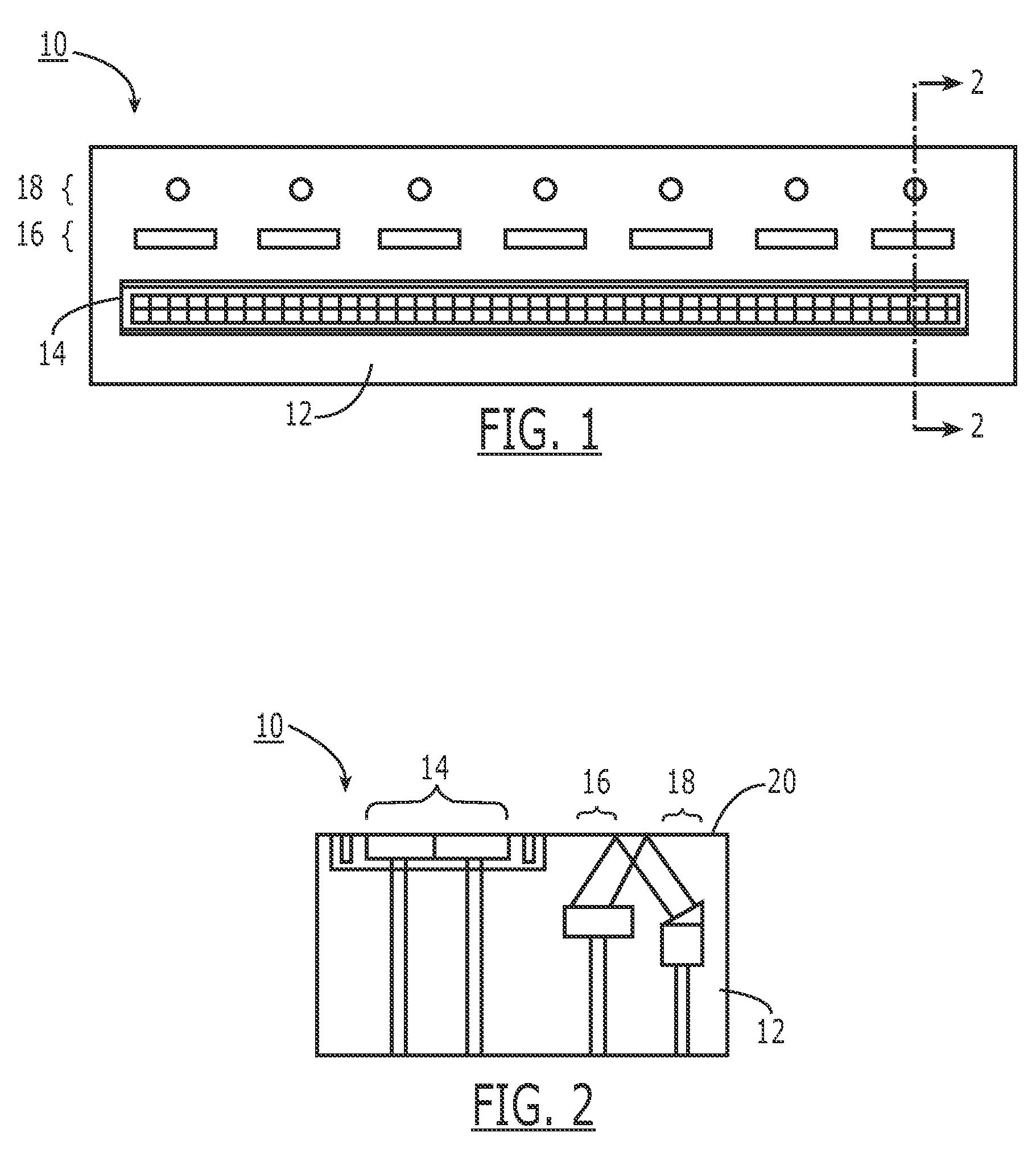
[0011]According to another aspect of the present invention in which an optical sensor and light source are disposed integrally in an enclosure with an electrical sensor structure, a sensor enclosure is comprised of a material, such as an appropriate plastic, which is transmissive at the wavelength(s) of light emitted by the light source. The enclosure material serves to mechanically hold the elements in their respective positions and provide durability and protection for those elements while permitting the sensor to sense light emitted by the light source through said enclosure material.
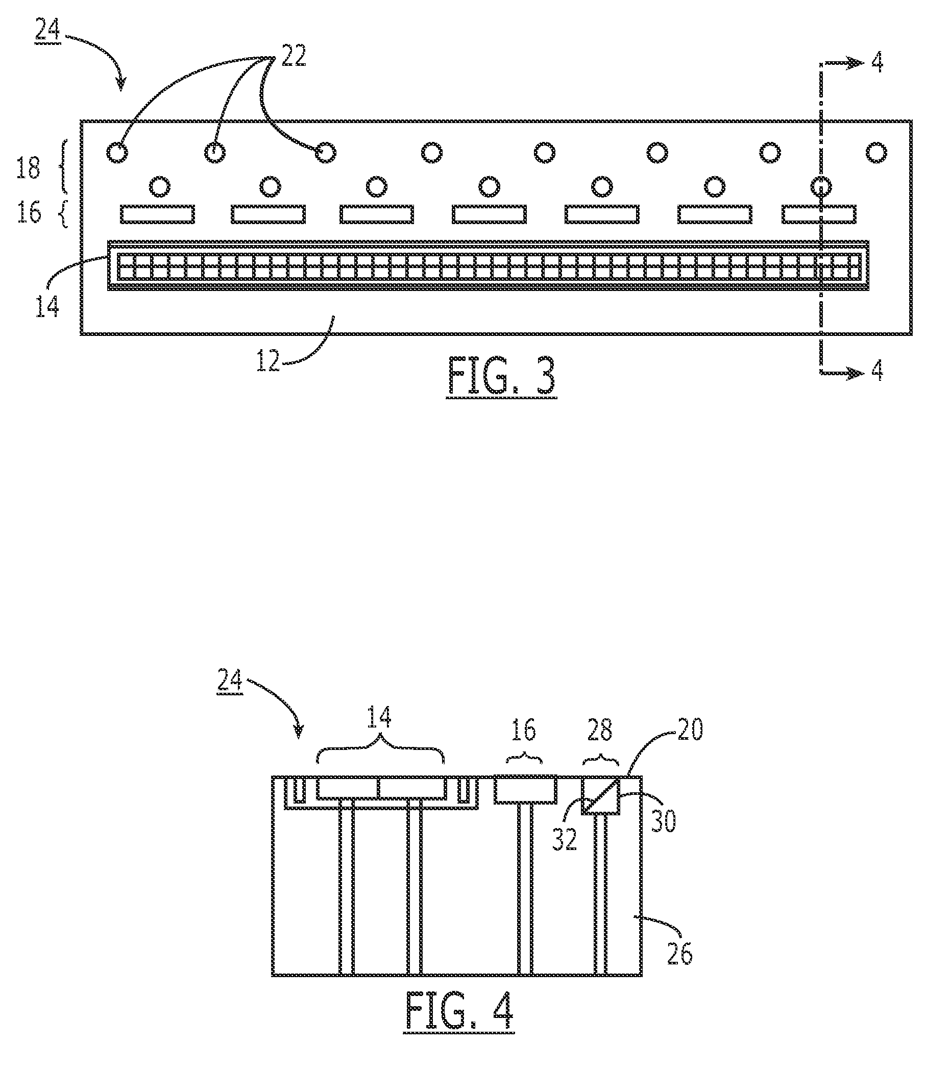
[0013]According to still another aspect of the present invention in which an optical sensor and light source are disposed integrally in an enclosure with an electrical sensor structure, the light source emits at one or more wavelengths visible to a user. The user may thus be provided cues to use of the sensor and feedback regarding successful or unsuccessful operation of the sensor. The sensor may also be provided with a visual uniqueness to enhance marketing and permit distinguishing the source of the sensor from other manufacturers or products.

Problems solved by technology

As each of the various optical and electrical sensing technologies have, to a greater or lesser extent, disadvantages which lead to errors in image construction and ultimately the possibility of misidentification a user, there is a virtually unending need to improve the accuracy of biometric sensing and identification.
Such replicated prints have historically been used to defeat the security of biometric identification systems, (so-called “spoofing”).
However, virtually as soon as a new anti-spoofing technique is deployed, an effort surfaces to defeat it.

Method used


Image

  • Hybrid multi-sensor biometric identification device
  • Hybrid multi-sensor biometric identification device
  • Hybrid multi-sensor biometric identification device

Examples


Embodiment Construction

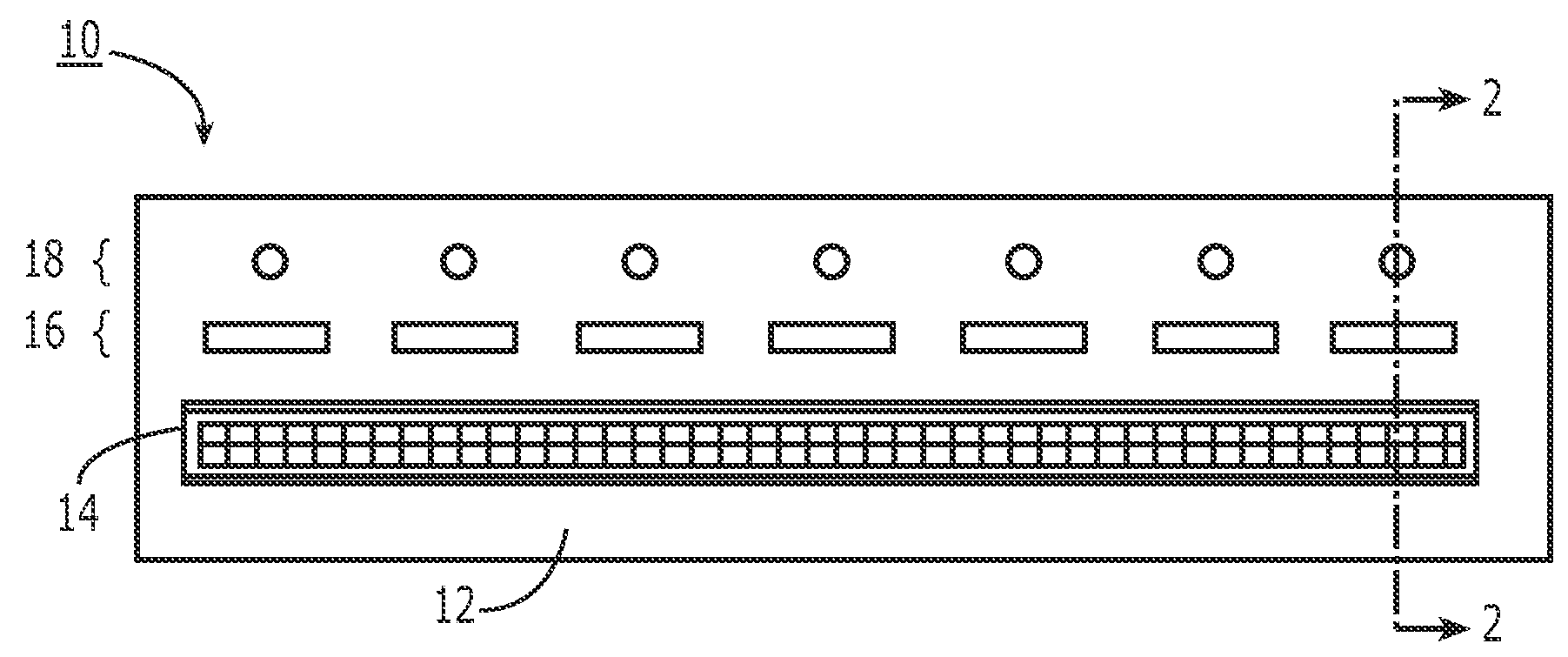
[0029]With reference to FIG. 1, a first embodiment 10 of a hybrid multi-sensor biometric identification device according to the present invention is illustrated. FIG. 1 is a top view of the device consisting of: a unitary body structure 12 having disposed therein an electrical sensor array 14, an optical sensor array 16, and a light source array 18, each described in further detail below. While the embodiment shown in FIG. 1 illustrates the basic principles of the invention, the specific arrangement of devices (e.g., relative placement, number of elements, etc.) is not critical to the broad concept of a hybrid electrical / optical fingerprint sensor according to the present invention.

[0030]According to one embodiment, body structure 12 will typically be a plastic, phenolic, acrylic, glass, or similar material providing mechanical support and protection for various elements placed or formed therein. The material may be fully or partially transmissive or opaque, depending on the arrange...


PUM


Abstract

An improved fingerprint sensing device is provided with multiple sensing apparatus, two or more of which operating on different sensing principles. For example, a capacitive sensor may be integrally formed with an optical sensor on a single substrate. Ideally, the multiple sensing apparatus are disposed such that they may sense nearly identical portions of a fingerprint simultaneously. A primary sensor may be employed to establish the identity of a user based on a fingerprint, while a secondary sensor may be employed to establish that the fingerprint is part of a live human (anti-spoofing). Integrated light sources may be provided to drive an optical sensor. The light sources may also provide visual cues for usage, and enhance the aesthetics of the device.

Description

BACKGROUND OF THE INVENTION[0001]1. Field of the Invention[0002]The present invention is related to devices for biometric identification, and more specifically to an integrated multi-sensor device, such as a hybrid optical and electronic sensor, which may be employed for biometric identification, authentication, etc.[0003]2. Description of the Prior Art[0004]It is well known that no two person's fingerprints are identical. The differences between two individuals' fingerprints can therefore be used to identify and distinguish individuals for a variety of applications. Two primary categories of fingerprint sensing technology exist today: electrical and optical.[0005]Broadly, optical sensing uses light (visible or otherwise) to capture an image of a user's fingerprint. For example, if a sufficiently intense light is incident on a user's finger, some of that light will be reflected. This reflection may be captured as an image and compared to a reference image to establish the identity o...

Claims


Application Information

Patent Timeline
IPC IPC(8): G06K5/00G06V40/13
CPCG06K9/00013A61B5/1172G06V40/13
Inventor KRAMER, ALANGOZZINI, GIOVANNI
Owner APPLE INC
Learn More