Travel unit for mobile machines

a technology for mobile machines and travel units, applied in the direction of machine supports, supplementary fittings, vehicle maintenance, etc., can solve the problem that the known design requires a large production effort, and achieve the effect of reducing production effort and minimizing manufacturing costs

Inactive Publication Date: 2009-07-02
LEIBHERR HYDRAULIKBAGGER GMBH
View PDF5 Cites 14 Cited by
  • Summary
  • Abstract
  • Description
  • Claims
  • Application Information

AI Technical Summary

Benefits of technology

[0006]It is the object of the present invention to further develop a mobile unit of the generic type such that support positions and components can be saved and thus a lower production effort is made possible which results in a minimization of manufacturing costs.
[0007]This object is solved in accordance with the invention by the combination of the features herein. Accordingly, a mobile unit for mobile machines having extensible support devices is equipped with a first, continuous rigid support on which some of the support devices are arranged and on which a further continuous support and the divided support arms, which support the remaining support devices, are outwardly pivotably linked. In accordance with the invention, the first, continuous rigid support is aligned at an angle to the imagined longitudinal axis of the mobile unit and the further continuous support or the divided support arms are aligned with point symmetry to a real or imagined pivot point on the continuous rigid support, with them likewise supporting travel devices. This new design distances itself from the customary construction concept of the mobile unit, which consisted, as a rule, of a complex welding design with longitudinal supports arranged rigidly with respect to one another and transverse supports connecting them together on which the turntable is supported. Since the support devices are arranged directly on the continuous rigid support and on the continuous support connected to it or on the linked divided support arm, a direct flow of force from the superstructure into the support devices is made possible, which represents a technical implementation of the tree root principle. This manner of design saves support positions and components, which results, on the one hand, to a lower production effort and thus also to lower manufacturing costs. Due to the inclined and thus asymmetric alignments of the first support and of the corresponding point-symmetrical association of either the second rigid support or the correspondingly linked divided support arms, with the latter each likewise supporting driving devices, a variable track width is possible by a pivoting of the supports with respect to one another. This variable track width can also be set under load. In desired positions, the whole mobile unit can be supported by a corresponding extension of the support apparatus.

Problems solved by technology

This known design requires a large production effort in particular due to the extensive components and support positions.

Method used


Image

  • Travel unit for mobile machines
  • Travel unit for mobile machines
  • Travel unit for mobile machines

Examples


Embodiment Construction

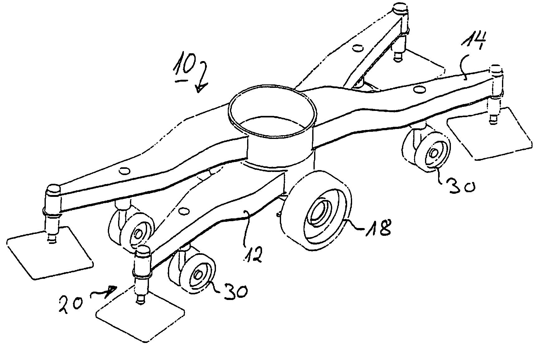
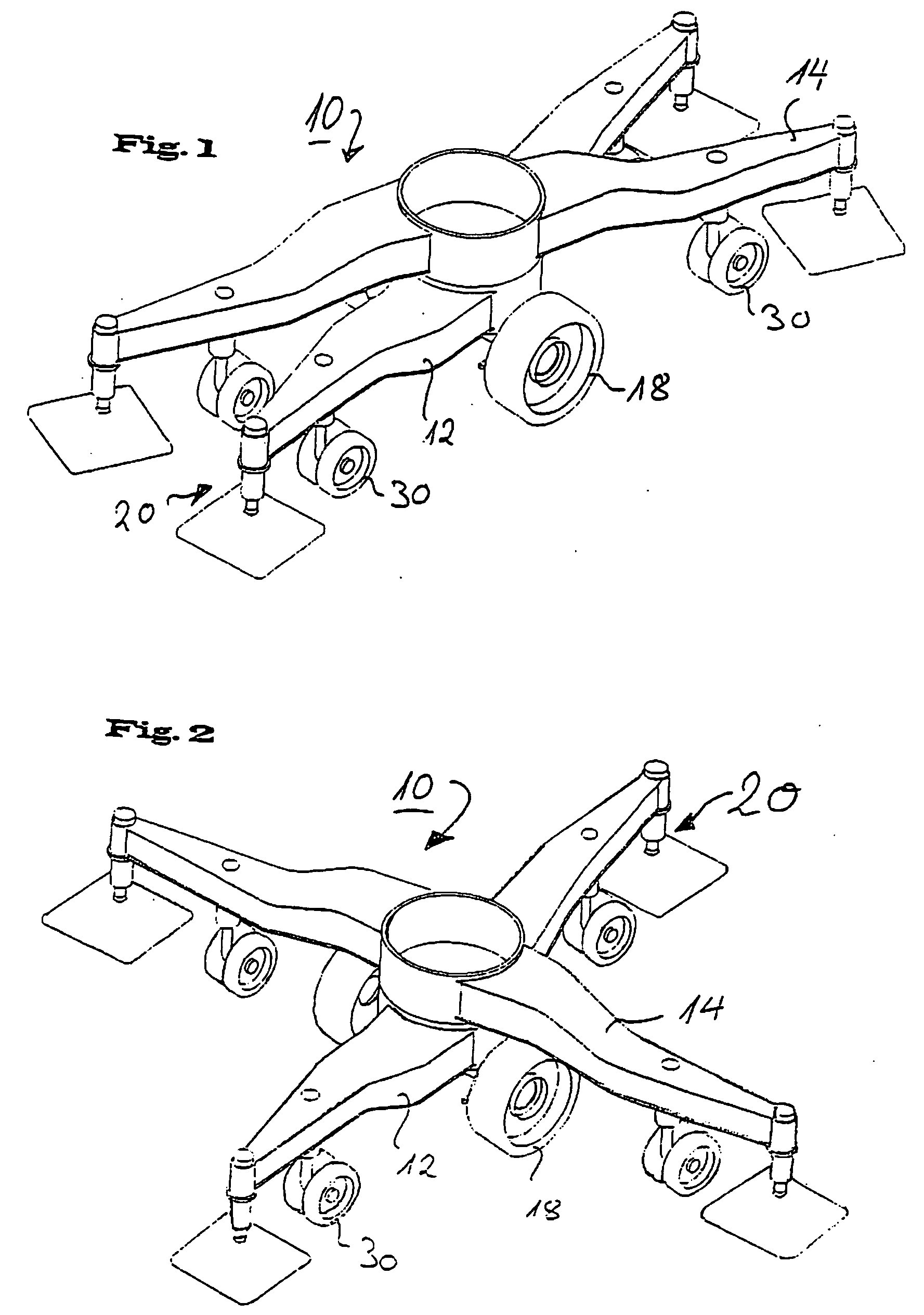
[0018]A first variant of a mobile unit 10 is shown in FIGS. 1 and 2 which has a rigid continuous support 12 which is pivotably connected to a second continuous rigid support 14 via a rotary joint not shown more closely in detail here. Support devices 20, which substantially consist of support plates 22 which can be extended or retracted via adjustment devices 24, are arranged on or after the respective ends of the continuous rigid supports 12 and 14.

[0019]The continuous rigid supports 12 and 14, which are connected to one another via spherical turntables, each have turntable supports 26 at their centers. The rotating deck of the superstructure of the machine can be placed in the usual manner on the turntable support 26 of the rigid continuous support 14. Since these are known designs, this is not shown in any more detail in the drawing.

[0020]A single wheel drive with individual wheels 18 is arranged by means of a further rotary joint which is not shown in any more detail here and wh...


PUM


Abstract

The invention relates to a mobile unit for mobile machines having extensible support devices comprising a first, continuous rigid support on which travel devices and some of the support devices are arranged and on which a further continuous support or divided support arms, which support the remaining support devices, are outwardly pivotably linked. In accordance with the invention, the first, continuous rigid support is aligned at an angle to the imagined longitudinal axis of the mobile unit and the further continuous support or the divided support arms are aligned with point symmetry to a real or imagined pivot point on the continuous rigid support, with them likewise supporting travel devices.

Description

CROSS-REFERENCE TO RELATED APPLICATION(S)[0001]The present application is a divisional application of co-pending U.S. application Ser. No. 11 / 089,638 filed Mar. 25, 2005.BACKGROUND OF THE INVENTION[0002]The invention relates to a travel unit for mobile machines having extensible support devices.[0003]Mobile machines such as hydraulic excavators, cable-operated excavators and other earthmovers and / or transfer units usually have a travel unit at which the travel devices, that is, for example, the wheels or, for example, crawlers, are arranged. The travel unit furthermore as a rule has a receiving plate for a turntable support on which the rotating deck with slewing gear belonging to the superstructure can be placed. This known design requires a large production effort in particular due to the extensive components and support positions.[0004]In another respect, the track width of the machine is, as a rule, fixed by the mobile unit and the running gear linked to it.[0005]A mobile crane ...

Claims


Application Information

Patent Timeline
Patent Type & Authority Applications(United States)
IPC IPC(8): B60S9/00B66C23/78E02F9/02E02F9/08E02F9/10E21D9/10F16M11/38
CPCE02F9/085B66C23/78
Inventor AUTENRIETH, OLIVER
Owner LEIBHERR HYDRAULIKBAGGER GMBH
Why Eureka
Try Eureka