
Occupational support system

Inactive Publication Date: 2009-07-02
COCHRAN DENNIS
View PDF46 Cites 2 Cited by
  • Summary
  • Abstract
  • Description
  • Claims
  • Application Information

AI Technical Summary

Benefits of technology

[0009]It is another aspect of the present invention to provide for an improved occupational support chair system for supporting the weight of a user from his or her front.
[0010]The aforementioned aspects and other objectives and advantages can now be achieved as described herein. An occupational support chair system that provides a frontal support to a user is disclosed. The support chair system can be configured to include a lower support frame composed of a dual section hydraulic frame and an upper support frame. The upper support frame can be configured in the form of a spinal column associated with a number of individual locking segments. The upper support frame can further include a breast support and a removable chin support in order to provide frontal support to the user. An adjustable swivel seat can be attached to the upper support frame to relieve stress and reduce fatigue stemming from prolonged periods of standing. The support chair system further includes a stabilizing base segment, which can include retractable wheels and a housing for batteries, electrical and computer components.
[0011]The upper support frame can include the use of a balancing sensor and a motion sensor, which can be utilized to detect the user's intent and to automatically adjust the position of the support system in accordance with a user's movement. The upper support frame can effectively reduce the strain at the lower back and shoulders of the user by changing its position. The breast support further includes individual rib segments that can be adjusted in and out in order to accommodate larger frames. The breast support can also be padded with technology foam for comfort. The dual section hydraulic frame of the lower support frame can be utilized to lift the user into a comfortable position.
[0012]The stabilizing base segment can be disposed in a horizontal plane and extend at a substantially common angle from the lower support frame to provide support to the support chair system. The retractable wheels of the stabilizing base segment can be deployed by the user by means of weight. The support system can be swiveled by lifting the weight of the user from the seat so that wheels in the stabilizing base segment can be deployed. The weight on the seat can cause the wheels to retract when the user is in an appropriate position, by rendering the support system immobile. The swivel adjustable seat can support the user's weight in a standing position through the use of an adjustable and pivoting mechanism. Such support system provides frontal breast support to relieve strain from the lower back and shoulders as a user leans over a patient or other subject.

Problems solved by technology

Conventional adjustable chairs provide sufficient comfort to the patients, but are not very useful to the surgeons, doctors and dentists.
For example, dentists and dental assistants working in dental clinics have suffered from back problems for years due to many hours leaning and twisting over patients while performing precise and delicate work on the patients' teeth.
Holding up the arms for prolonged periods of time creates further stress and tension on the lower back, shoulders and neck resulting in stinging pains in these areas.
Hence, surgeons, doctors and dentists may be forced to quit their respective occupations due to lower back, neck and shoulder problems stemming from years of leaning over surgery tables and standing or sitting for prolonged periods.
The majority of prior art support chair systems include a lumber back support, which does not provide an endurable amount of support for a user's weight from the front.
Such chairs typically do not attain their intended purpose of back support due to erroneous design problems.
That is, the support system for such devices generates a huge strain at the lower back and shoulders of the user while leaning over, for example, a patient.
Such support chair assemblies suffer from a number of disadvantages, including a limited freedom of movement when a user is seated on the chair and performs a work task forward of the seating surface.

Method used


Image

  • Occupational support system
  • Occupational support system
  • Occupational support system

Examples


Embodiment Construction

[0018]The particular values and configurations discussed in these non-limiting examples can be varied and are cited merely to illustrate at least one embodiment and are not intended to limit the scope thereof.

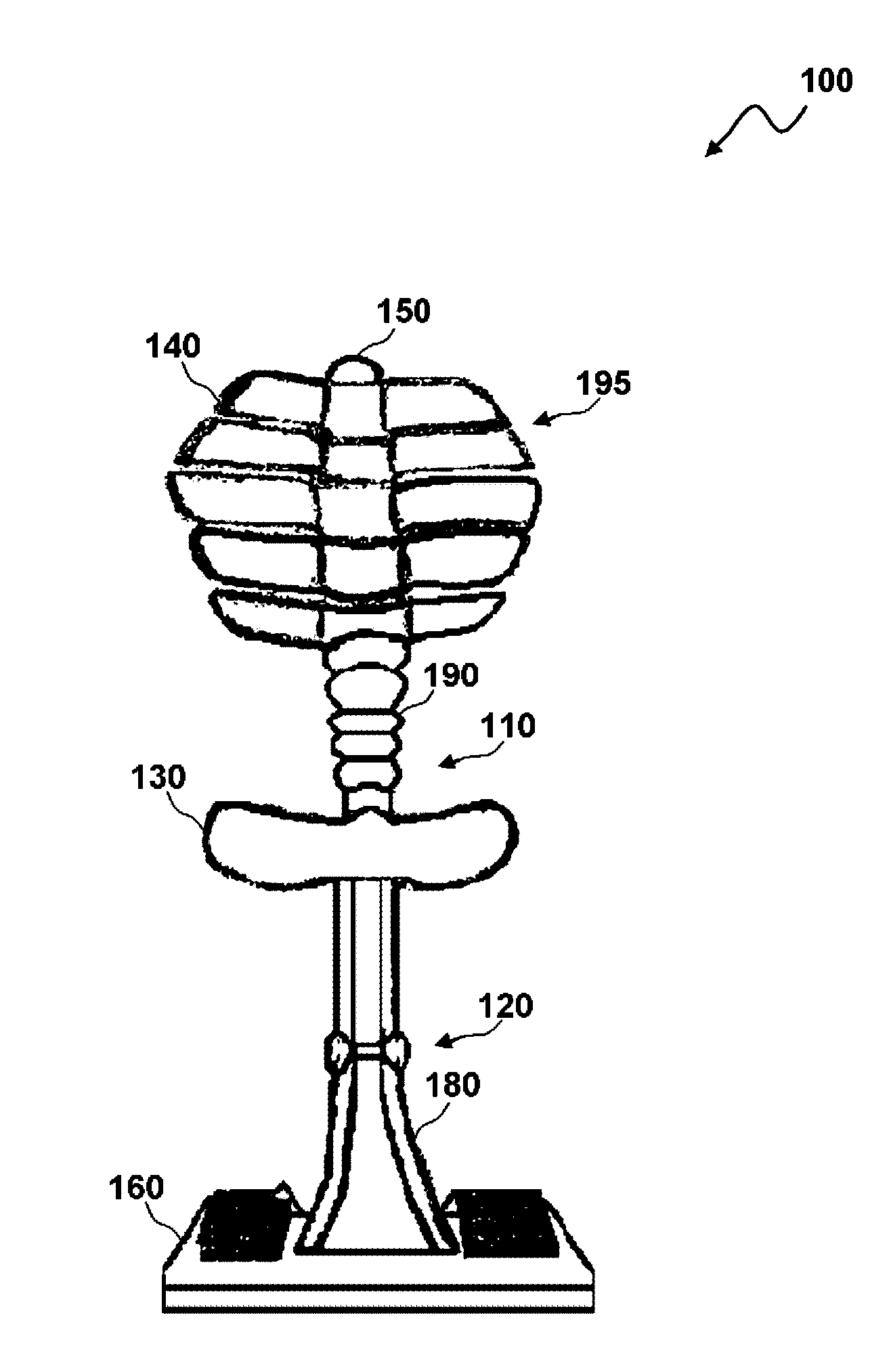
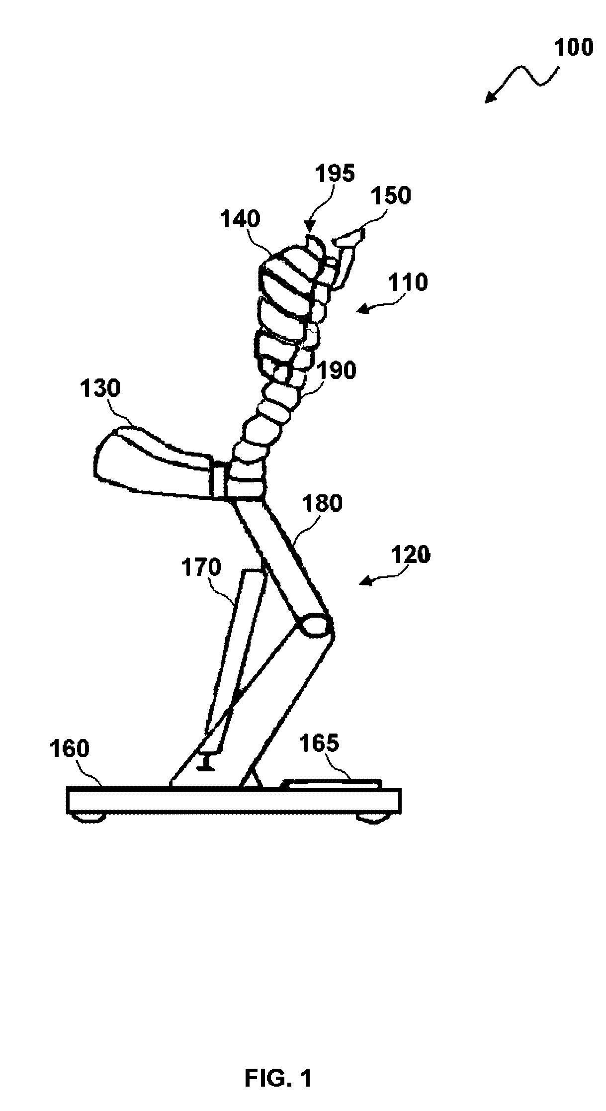
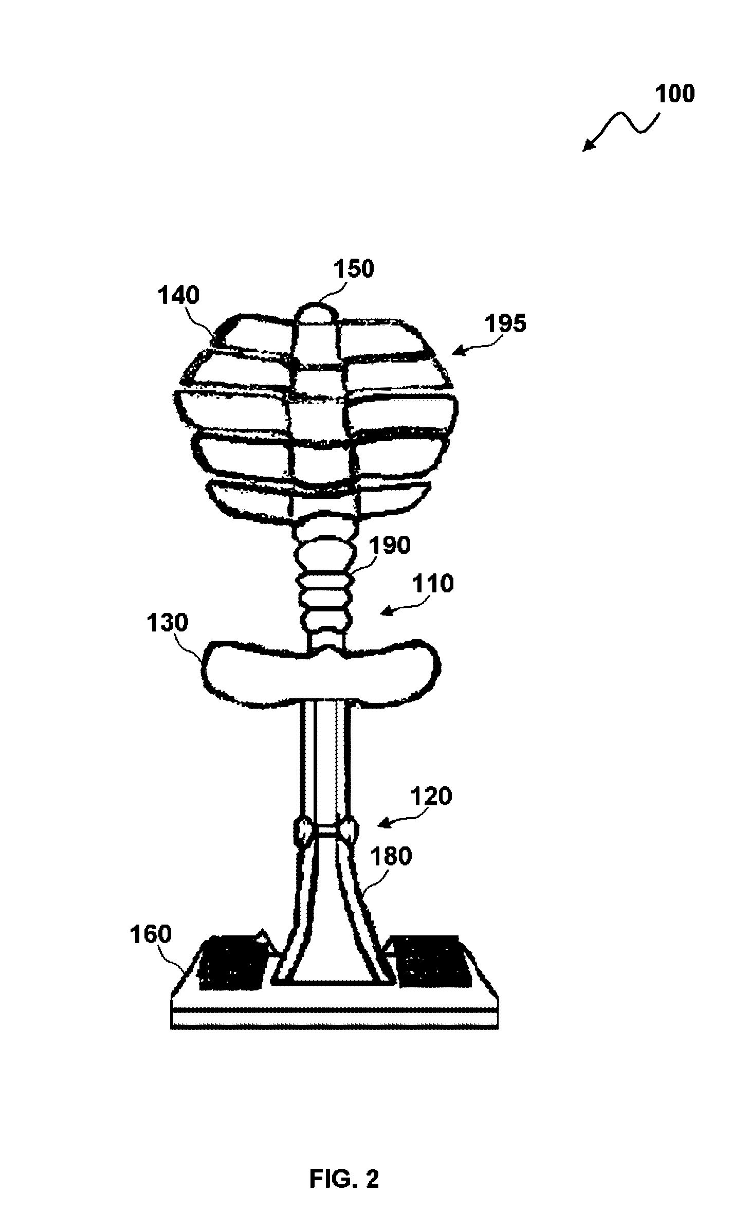
[0019]FIG. 1 illustrates a side view of an occupational support chair system 100, which can be implemented in accordance with a preferred embodiment. The occupational support system 100 generally includes an upper support frame 110, a lower support frame 120 and a stabilizing base 160. The upper support frame 110 further includes a breast support 195 that is capable of providing frontal support to a user and alleviating the stress at the user's lower back and shoulders. The upper support frame 110 can be configured in the form of spinal column utilizing individual locking segments 190.

[0020]The breast support 195 can be configured to include individual rib segments such as, for example, rib segment 140. The individual locking segments 190 of the upper support frame 110 can chan...


PUM


Abstract

An occupational support chair system and method that provides frontal support to a user. The support chair system includes a lower support frame composed of a dual section hydraulic frame and an upper support frame. The upper support frame can be configured as a spinal column associated with a number of individual locking segments. The upper support frame further includes a breast support and a removable chin support in order to provide frontal support to the user. An adjustable swivel seat can be attached to the upper support frame to relieve stress and fatigue stemming from prolonged periods of standing. The support chair system further includes a stabilizing base segment, which comprises retractable wheels and a housing for batteries, electrical and computer components.

Description

CROSS-REFERENCE TO PROVISIONAL APPLICATION[0001]This application claims priority under 35 U.S.C. §119(e) to U.S. Provisional Patent Application No. 61 / 016,655 filed on Dec. 26, 2007 and entitled “Occupational Support System,” which is hereby incorporated by reference in its entirety.TECHNICAL FIELD[0002]Embodiments are generally related to adjustable support chairs suited for use in medical and dental applications, beauty parlors, barbershops, and so forth.BACKGROUND OF THE INVENTION[0003]Adjustable chairs are utilized in a wide variety of applications such as, for example, medical and dental applications, beauty parlors and barbershops, and the like, in order to provide an efficient and comfortable treatment. In medical and dental applications, for example, the adjustable chair is utilized to support a patient's body in an upright, supine position (reclined position with nose and knees on the same plane) or sub-supine position (reclined position with head lower than the feet), whic...

Claims


Application Information

Patent Timeline
IPC IPC(8): A47C7/50A47C31/00
CPCA47C9/005A47C7/38
Inventor COCHRAN, DENNIS
Owner COCHRAN DENNIS
Learn More