
Image converter and image converting method

a technology applied in the field of image converter and image converting method, can solve the problems of poor user operability, distorted circular images of fisheye lenses photographed by use of fisheye lenses, etc., and achieve the effect of reducing the operation load of conversion

Inactive Publication Date: 2009-07-02
DAI NIPPON PRINTING CO LTD
View PDF6 Cites 21 Cited by
  • Summary
  • Abstract
  • Description
  • Claims
  • Application Information

AI Technical Summary

Benefits of technology

[0008]An object of the present invention is to provide an image converter and an image converting method capable of setting necessary parameters by an intuitive manipulation of a user and also capable of reducing the operation load on conversion of a distorted circular image photographed by use of a fisheye lens to a planar regular image.

Problems solved by technology

However, images photographed by use of a fisheye lens are distorted in circular images, and the images may be used for artistic pictures, as they are, but not suitable for general photographic uses.
Thereby, such a problem is posed that the operability is poor for a user.
Another problem of conventional image converters is operation load.
However, these transformation equations are complicated equations including trigonometric functions for three angles α, β, ψ, thereby imposing a substantially great operation load to a system.
As a result, there is posed a serious problem in reducing the production cost.

Method used


Image

  • Image converter and image converting method
  • Image converter and image converting method
  • Image converter and image converting method

Examples


Embodiment Construction

[0117]Hereinafter, a description will be given for embodiments which illustrate the present invention.

>>

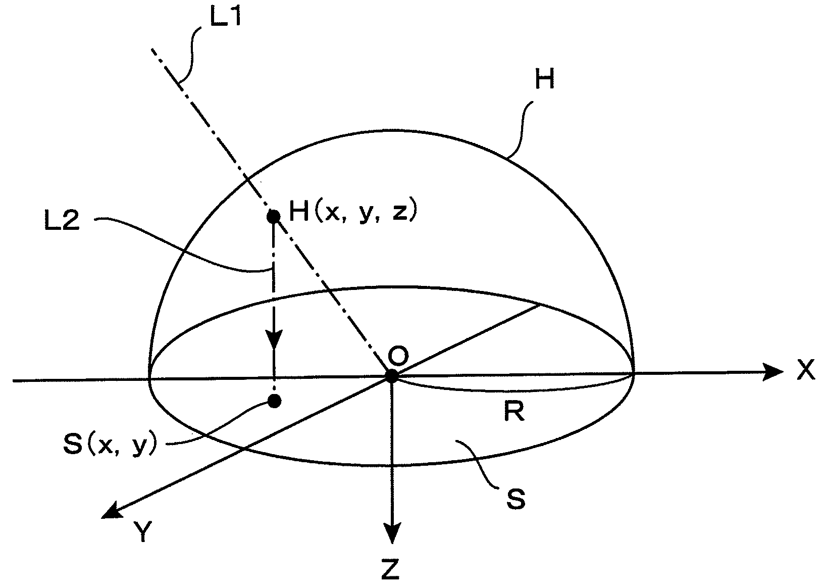
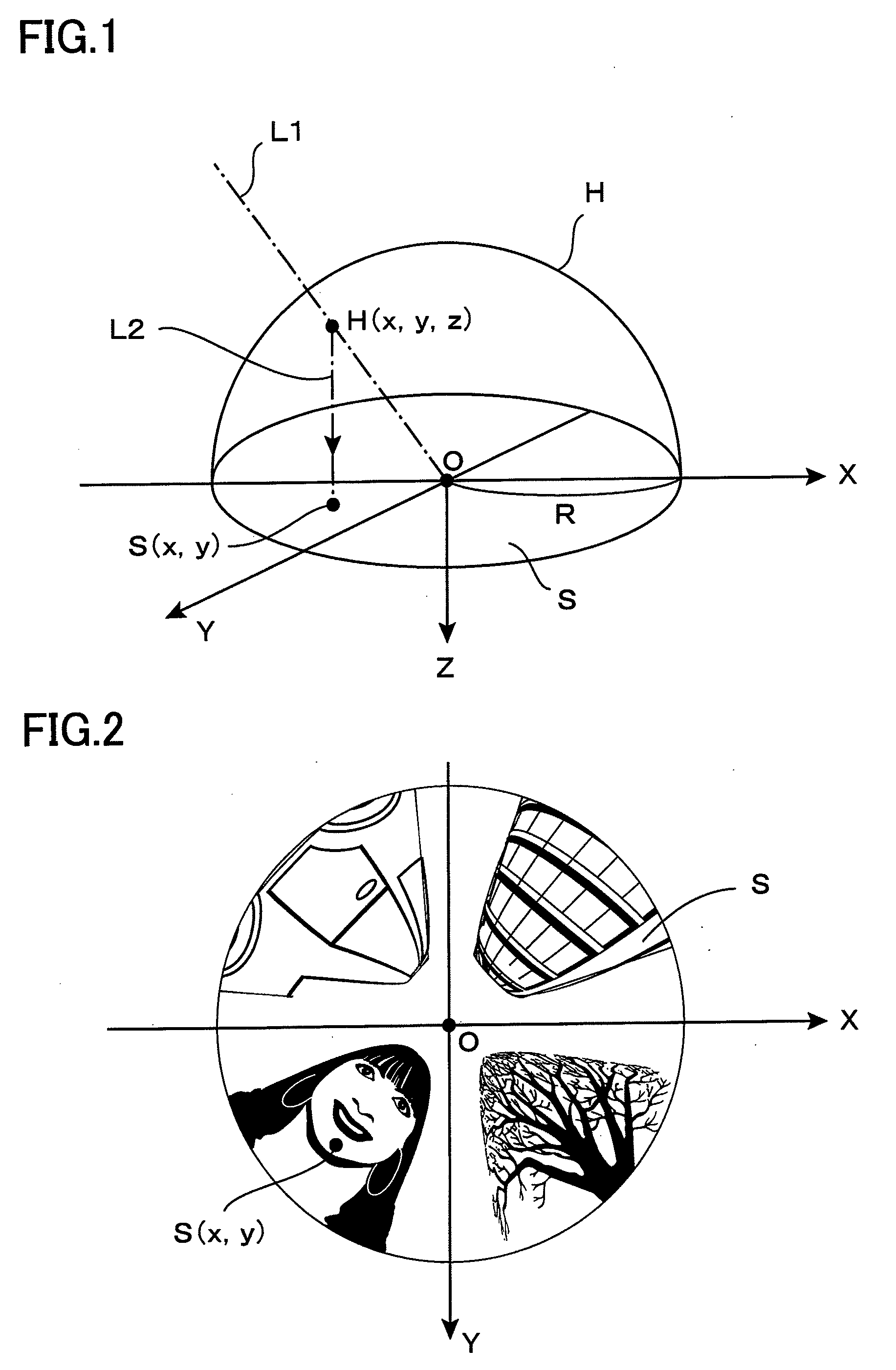
[0118]First, a description will be given for general characteristics of a distorted circular image photographed by use of a fisheye lens and a basic principle of cutting out a part thereof and converting it into a planar regular image. FIG. 1 is a perspective view showing a basic model of forming a distorted circular image S by photographing by use of a fisheye lens based on the orthogonal projection method. In general, fisheye lenses are classified into plural types, depending on projection methods thereof. The model shown in FIG. 1 is a fisheye lens based on the orthogonal projection method (a method for applying the present invention to fisheye lens based on projection other than those based on the orthogonal projection method will be described in Section 5).

[0119]FIG. 1 shows an example in which a distorted circular image S is formed on the XY plane in a three-dimensional XYZ ...


PUM


Abstract

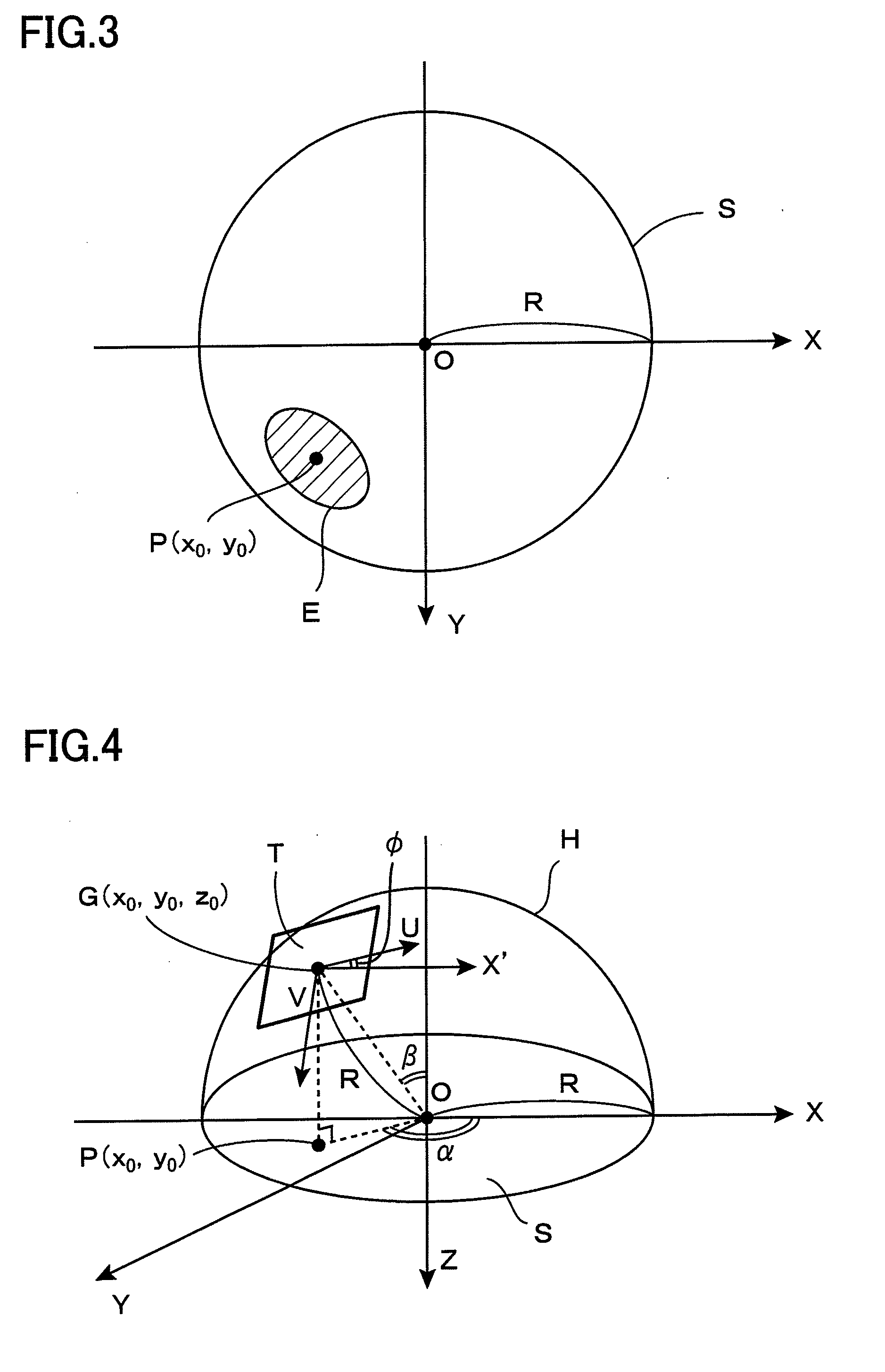
On conversion of a distorted circular image photographed by use of a fisheye lens to a planar regular image, parameter setting is performed by a user's intuitive manipulation to relieve the operation load. A dome-shaped virtual sphere H is defined on a distorted circular image S on the XY plane, and a user is allowed to designate a cut-out center point P (x0, y0) and an auxiliary point Q (x1, y1) on the distorted circular image S. An intersecting point G (x0, y0, z0) immediately above the point P is determined, and a UV plane is defined on a tangent plane S2 with respect to the virtual sphere H. An angle φ formed between the U axis and the X axis is determined on the basis of an angle θ formed between a reference straight line J passing through two points P, Q and the X axis. Transformation equations based on the orthogonal projection method including the coordinate values x0, y0, z0 and the angle φ as parameters are utilized to allow the coordinates (u, v) to correspond to coordinates (x, y), a distance between the two points P, Q is given as a conversion magnification m, thereby a part in the vicinity of the point P of the distorted circular image S is converted to a plane regular image on the UV plane.

Description

BACKGROUND OF THE INVENTION[0001]The present invention relates to an image converter and an image converting method and in particular to a technique for conducting processes of cutting out a part of a distorted circular image photographed by use of a fisheye lens and converting it into a planar regular image.[0002]A fisheye lens can be used to obtain hemispherical circular images in all directions without using a mechanical moving mechanism. Therefore, a fisheye lens has been extensively used in photographing scenic pictures and others aiming at eccentric effect. However, images photographed by use of a fisheye lens are distorted in circular images, and the images may be used for artistic pictures, as they are, but not suitable for general photographic uses.[0003]Thus, there has been proposed an apparatus for conducting processes of cutting out a part of a distorted circular image photographed by use of a fisheye lens and converting it into a planar regular image. For example, Inter...

Claims


Application Information

Patent Timeline
Patent Type & Authority Applications(United States)
IPC IPC(8): H04N5/228G06K9/32H04N23/40
CPCG06T3/0031G06T3/06H04N1/387
Inventor TONOMURA, MOTONOBU
Owner DAI NIPPON PRINTING CO LTD
Learn More