
Method and apparatus with depth map generation

a technology of depth map and depth map, applied in the field of methods and apparatuses with depth map generation, can solve the problems of short and fixed focal length, drastic impact on battery usage, power drain of mobile devices,

Active Publication Date: 2009-07-02
QUALCOMM INC
View PDF10 Cites 93 Cited by
  • Summary
  • Abstract
  • Description
  • Claims
  • Application Information

AI Technical Summary

Problems solved by technology

Such cameras have a wide angle lens that results in a short and fixed focal length.
Capturing 10 or so images from which the auto focus algorithm determines the best image can result in power drain for the mobile device and over time drastically impact battery usage.
In addition, if the flash is used to take the final image, when a flash may not actually be necessary or useful, the additional power drain can degrade the performance of the mobile device.
This can require additional processing time and the user may have to wait an unnecessary amount of time for the auto focus operation to be completed.
The searching method can affect the speed and accuracy of auto-focus process.
However, it can be difficult to determine the rates of change and then determine a suitable interval to use.
However, known current solutions still can require unnecessary amounts of time and / or power consumption.
Generating depth maps using such systems can result in a highly complex and expensive process requiring multiple pre-calibrated cameras.

Method used


Image

  • Method and apparatus with depth map generation
  • Method and apparatus with depth map generation
  • Method and apparatus with depth map generation

Examples


Embodiment Construction

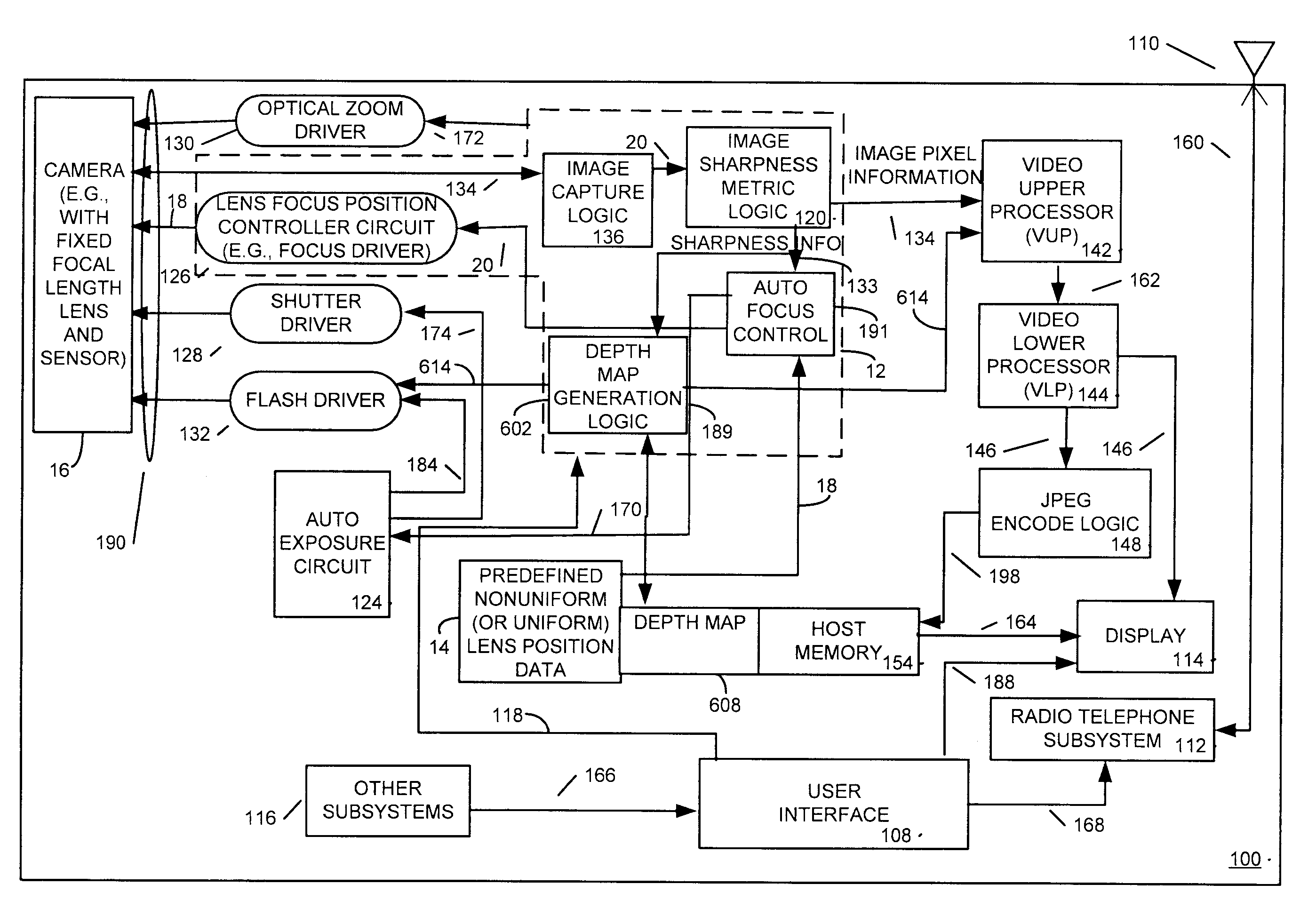
[0019]Generally, an apparatus and method are disclosed wherein a depth map is generated using a single camera (e.g., single lens of a camera) and multiple images are captured by the camera. In one example, a single digital camera is used to capture a set of images corresponding to a set of lens positions based on lens position data. In this example, the lens position data may be either uniform or nonuniform lens position data. The method and apparatus determines focus metric information for each of a plurality of regions of interest in each image of a set. A determination is made of a best lens position for each of the regions of interest based on the focus metric information from the images in the set and are stored as data in a depth map. Image generation operations are then performed based on the generated depth map, such as determining whether or not to use a flash to capture a final image, to determine a type of color operation to be performed on the final image, or any other s...


PUM


Abstract

An apparatus and method are disclosed wherein a depth map is generated using a single camera (e.g., single lens of a camera) and multiple images are captured by the camera. In one example, a single digital camera is used to capture a set of images corresponding to a set of lens positions based on lens position data. In this example, the lens position data may be either uniform or nonuniform lens position data. The method and apparatus determines focus metric information for each of a plurality of regions of interest in each image of a set. A determination is made of a best lens position for each of the regions of interest based on the focus metric information from the images in the set and are stored as data in a depth map. Image generation operations are then performed based on the generated depth map, such as determining whether or not to use a flash to capture a final image, to determine a type of color operation to be performed on the final image, or any other suitable image generation operation. In one example, the depth map is generated by selecting a best focus metric among the various images that were captured for a particular region of interest. Once the depth map is generated using data from the multiple images, depth map based control logic then determines how to use the depth map to effect an image processing operation. Among other advantages, multiple cameras need not be employed nor do external light sensors need be employed to generate a depth map for use in image processing operations. Other advantages will be recognized by those of ordinary skill in the art.

Description

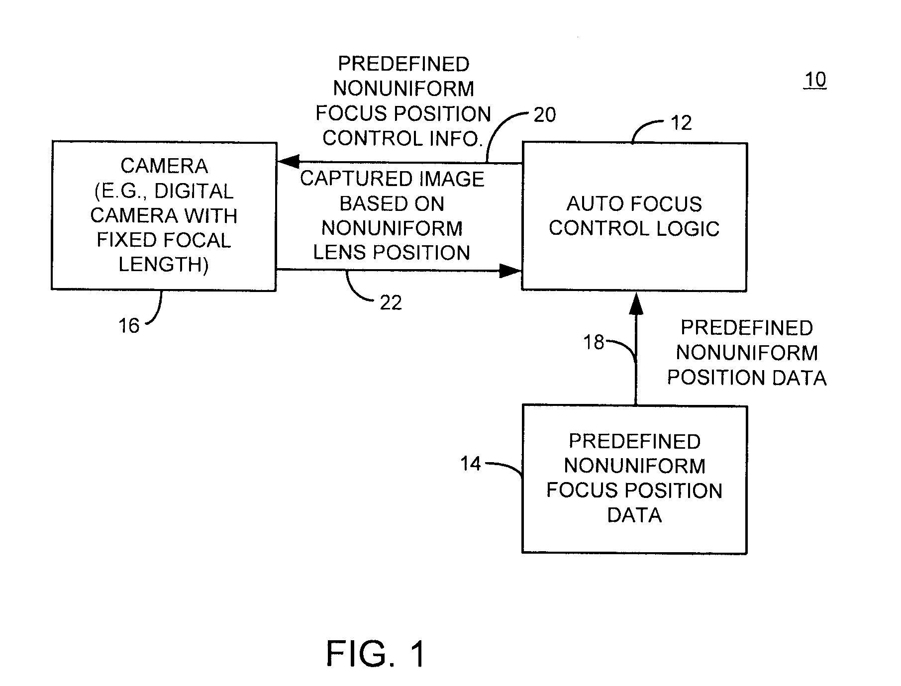
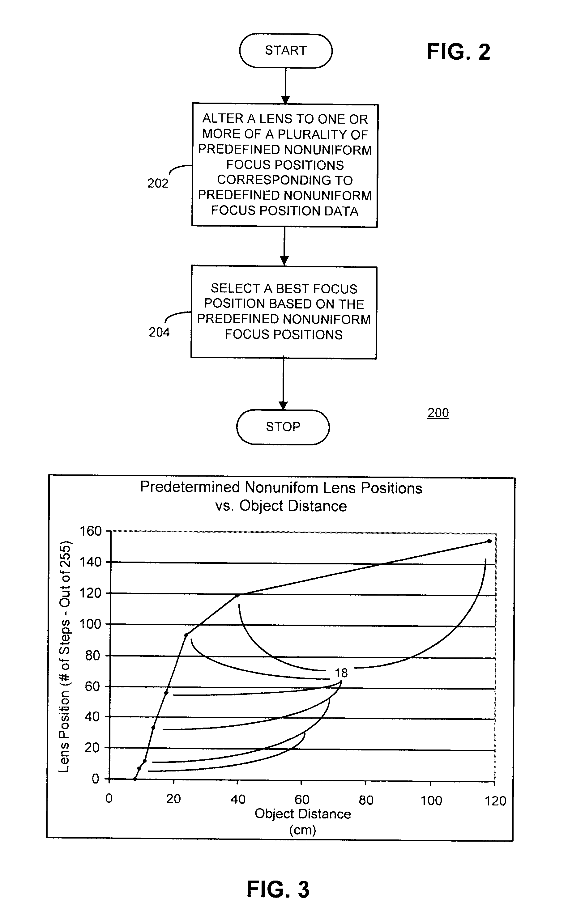
RELATED CO-PENDING APPLICATIONS[0001]This application is related to co-pending application entitled “METHOD AND APPARATUS WITH FAST CAMERA AUTO FOCUS”, filed on even date, having docket number 00100.07.0059, inventors Reza Safaee-Rad et al., owned by instant Assignee and is incorporated herein by reference.BACKGROUND OF THE INVENTION[0002]Digital cameras that employ fixed focal length lenses are used in mobile devices such as cell phones, laptops and other devices. Such cameras have a wide angle lens that results in a short and fixed focal length. Auto focus operations are known wherein a user of the cell phone or digital camera may hold down a push button halfway to auto focus an image whereafter the user may then continue to press the button to the fully pressed position to capture the final image. However, known auto focus operations may move the lens in a uniform manner such as every 25 positions throughout its range of, for example, 255 positions and capture an image at every u...

Claims


Application Information

Patent Timeline
IPC IPC(8): H04N5/232
CPCG06T7/0069G06T2207/10012G06T2207/10016H04N5/23212H04N2213/003H04N13/0048H04N13/0059G02B27/0075H04N5/2356G06T7/571H04N13/194H04N13/161H04N23/676H04N23/673H04N23/743H04N13/236H04N23/00
Inventor SAFAEE-RAD, REZAALEKSIC, MILIVOJE
Owner QUALCOMM INC
Learn More