Printing system, printing apparatus, and preview method for printing system

Active Publication Date: 2009-07-02
CANON KK
6 Cites 9 Cited by

AI-Extracted Technical Summary

Problems solved by technology

If the reduction ratio is high when displaying the reduced image of a longitudinally long-sized page, the reduced image of the longitudinally long-sized page becomes a line, and the user cannot grasp the contents of the page.
As shown in FIG. 26, if the size is greatly different between pages, like A0 and A4 sizes, when displaying a list of pages of a document as reduced images, the image of a small-sized page becomes excessiv...

Method used

[0132]By the page list reduced image display processing (step S105) according to the first embodiment, the segment size for displaying the reduced image of a page becomes an integer multiple of the segment unit size on the basis of the ratio of the width and height of the page. Even when displaying the reduced image of a longitudinally long-sized page, visual perceptibility is not spoiled.
[0134]When displaying a list of reduced images, the list is generally displayed with blanks of the same width between reduced images in order to improve visual perceptibility, as shown in FIG. 14. When all the display area sizes of reduced images are equal to each other, the same blank width can be set by setting in adv...

Benefits of technology

[0023]Embodiments of the invention are advantageous since, when displaying the reduced image of a longitudinally long-sized page, a segment size for displaying a reduced image becomes an integer multiple of a segment unit size in accordance with the ratio of the width and height of the page. Even if the reduction ratio is high, the reduced image of the longitudinally long-sized page does not become a line.
[0024]In addition, a failure in visually perceiving page contents can be prevented by embodiments of the invention. The segment size and enlargement/reduction ratio for displaying a reduced image are determined for each page. Thus, embodiments of the invention can address page contents that...

Abstract

A printing system configured to set a segment unit size serving as a unit of a display area for displaying, as images, a list of pages which form the document; acquire a width and a height of each page image from the document data; calculate, when a value of a ratio of the width and the height of the page acquired in the acquiring exceeds a predetermined value, a display area size having a display region larger than the segment unit size; determine, for a page having the value of the ratio exceeding the predetermined value, an enlargement/reduction ratio so as to fit the page into the display area size; and display, a list of pages which form the document, by enlarging or reducing the page based on the enlargement/reduction ratio determined in the determining and displaying the page in a display screen at the display area.

Application Domain

Technology Topic

Image

  • Printing system, printing apparatus, and preview method for printing system
  • Printing system, printing apparatus, and preview method for printing system
  • Printing system, printing apparatus, and preview method for printing system

Examples

  • Experimental program(4)

Example

[0099]A first embodiment of the present invention will be described below referring to the drawings.
[0100]FIG. 8 is a flowchart for explaining an outline of preview processing.
[0101]Assume that a reduced image is displayed in the vertical direction, and the user interface shown in FIG. 6 is used. When displaying a reduced image in the horizontal direction, the user interface shown in FIG. 7 is used.
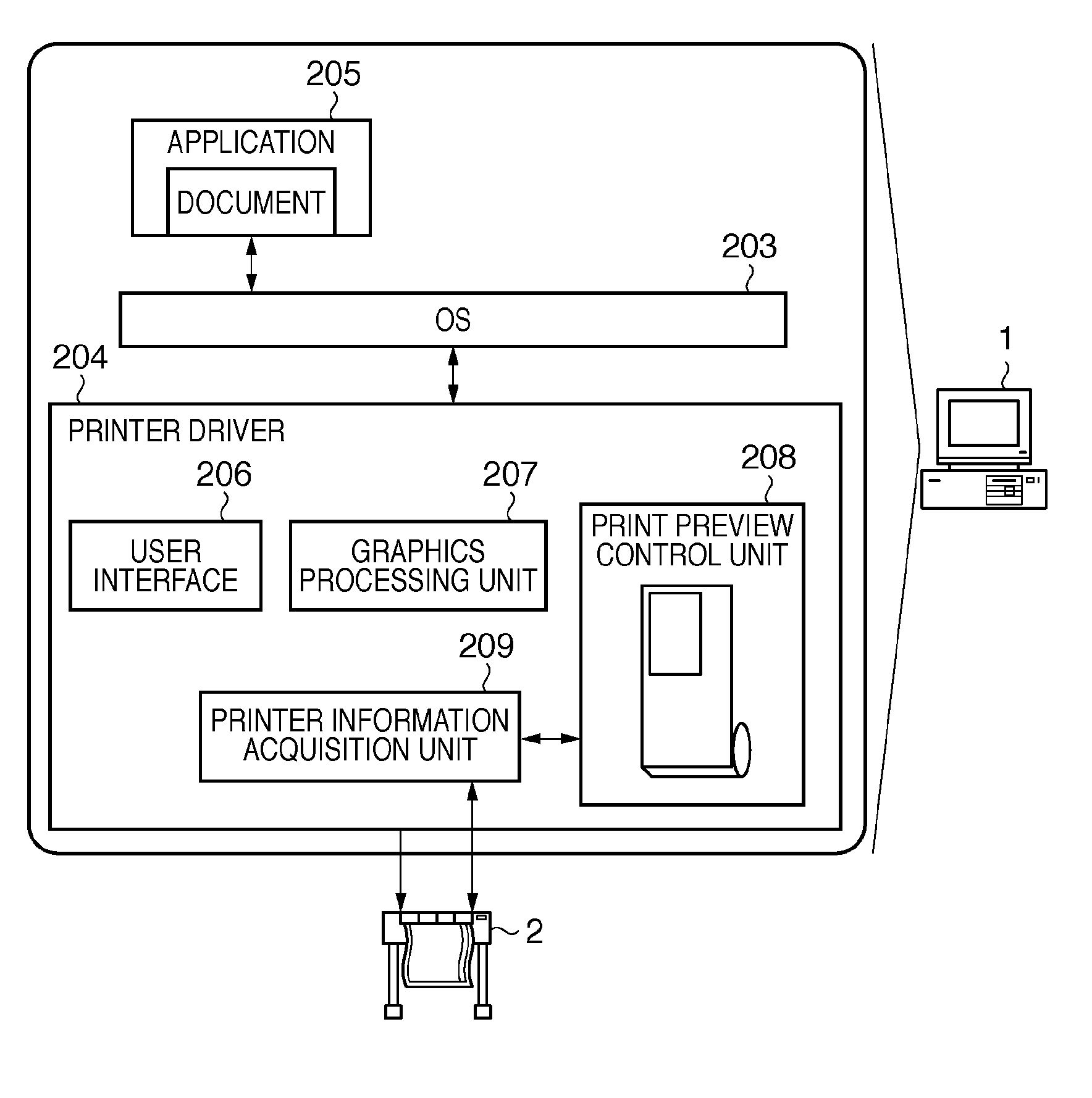
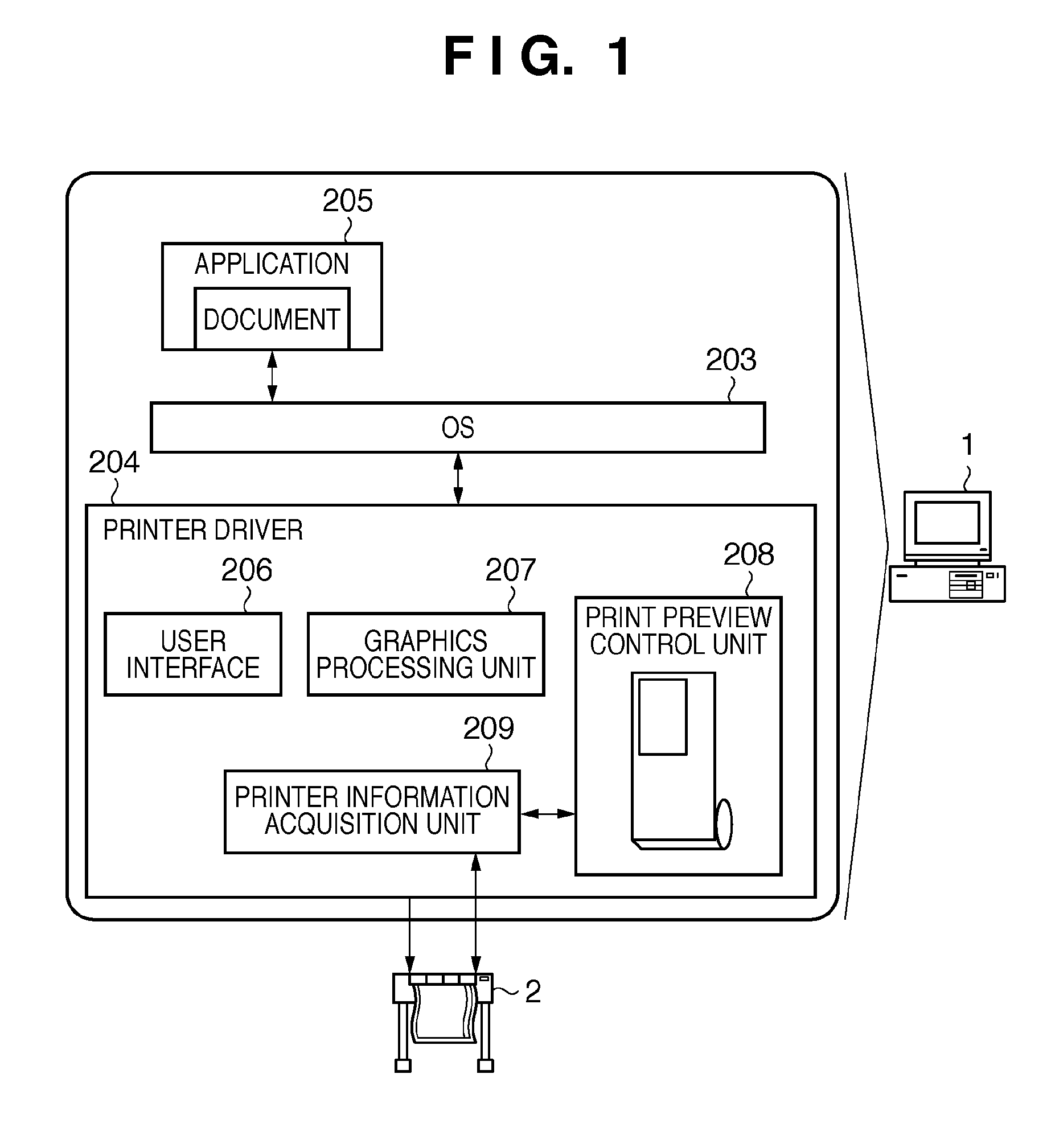
[0102]In step S101, a print preview dialog 501 is displayed. In step S102, printer driver settings are acquired from a user interface 206. Acquired paper source information is set in a paper source list box 505. Assume that “roll paper” is set.
[0103]It is inquired of a printer information acquisition unit 209 in step S103 whether or not printer information can be acquired from the printer main body.
[0104]If acquirable, printer information such as roll paper width information is acquired in step S104. If it is determined not to be able to acquire information from the printer main body, roll paper width information set in a “roll paper width” list box 404 in the printer driver setting information acquired in step S102 is used.
[0105]Based on the acquired printer information, the current printer status is displayed in a printer information display text box 507. Roll paper width information acquired from the printer main body or roll paper width information in the printer driver setting information is set in a roll paper width list box 506. Assume that “17 inches” is set.
[0106]In step S105, page list reduced image display processing is performed.
[0107]Details of this processing will be described later.
[0108]After the end of the page list reduced image display processing in step S105, print preview display processing is executed in step S106. By this processing, the paper image 503 which reflects the paper source and roll paper width set in the paper source list box 505 and roll paper width list box 506 is displayed. It is previewed in the paper image 503 how a document containing data 901 and 904 is printed. Then, the process of the system ends.
[0109]The page list reduced image display processing in step S105 will be explained.
[0110]FIG. 9 is a flowchart showing details of the page list reduced image display processing.
[0111]FIG. 10 is a flowchart showing a modification of steps S705 to S707 in FIG. 9.
[0112]FIG. 11 is a view showing a document transferred to the print preview control unit.
[0113]In FIG. 11, reference numeral 901 denotes the first page of the document; 902, a width of the first page; and 903, a height of the first page. Reference numeral 904 denotes the second page of the document; 905, a width of the second page; and 906, a height of the second page.
[0114]FIG. 12 is a view showing the size of a segment unit.
[0115]As shown in FIG. 12, according to the first embodiment, a segment unit size serving as the unit of a display area size can be set from a user interface. In FIG. 12, a width 1002 of a segment unit size 1001 is 90 pixels, and a height 1003 of the segment unit size is 120 pixels.
[0116]Details of the page list reduced image display processing will be explained with reference to flowcharts shown in FIGS. 9 and 10.
[0117]In step S701, the segment unit size is determined. In this case, the segment unit size is set to one shown in FIG. 12.
[0118]In step S702, the first page of the document is set as a page to be processed. In this case, the first page 901 is set as a page to be processed.
[0119]In step S703, the width and height of the page are acquired. In this case, the width 902 and height 903 of the page 901 to be processed are acquired. The width is 2,480 pixels, and the height is 3,508 pixels.
[0120]In step S704, the ratio of the width and height of the page is calculated. In this case, the ratio of the width and height of the page is 2480:3508.
[0121]In step S705, a display area size having a display region which is an integer multiple of the segment unit size is calculated from the calculated ratio of the width and height of the page. Since the value of the ratio of the width and height of the page is not less than 1/4, the process advances to step S707, and the display area size is set equal to the segment unit size.
[0122]When displaying a reduced image horizontally, the processes in steps S705 to S707 are replaced with those in the flowchart shown in FIG. 10.
[0123]More specifically, in step S705′, a display area size having a display region which is an integer multiple of the segment unit size is calculated. In this case, the multiple is calculated depending on whether the value of the ratio of the width and height of the page is equal to or greater than 4/1. If the value of the ratio of the width and height of the page is equal to or greater than 4/1, the process advances to step S706′ to set the display area size double the segment unit size in the horizontal direction. After that, the process advances to step S708. If the value of the ratio of the width and height of the page is less than 4/1, the process advances to step S707′ to set the display area size equal to the segment unit size. Then, the process advances to step S708.
[0124]In step S708, the enlargement/reduction ratio at which the page inscribes the display area is calculated. The enlargement/reduction ratio at which a page having a width of 2,480 pixels and a height of 3,508 pixels inscribes a display area having a width of 90 pixels and a height of 120 pixels is calculated to be 3.42%. In step S709, the page 901 is reduced at the calculated enlargement/reduction ratio of 3.42%. In step S710, the reduced page is displayed in the display area.
[0125]FIG. 13 shows a reduced image display portion 509 which displays the reduced image of a page.
[0126]In FIG. 13, reference numeral 1101 denotes a display area of the first page document. The display area 1101 displays a reduced image 1102 of the first page document.
[0127]Thereafter, the process advances to step S711 to determine whether or not the currently processed page is the final one. Since the second page 904 follows the first page, the process advances to step S712 to set the next second page 904 of the document as a page to be processed. In step S713, a blank is inserted before the next display area. In this case, a 20-pixel blank 1103 is inserted in the vertical direction below the first page document display area 1101.
[0128]Then, the process returns again to step S703 to acquire the width and height of the second page 904 to be processed. In step S704, the ratio of the width and height of the page is calculated. In step S705, a display area size having a display region which is an integer multiple of the segment unit size is calculated from the calculated ratio of the width and height of the page. Since the ratio of the width and height of the page is 2480:10524, and the value of the ratio is less than 1/4, the process advances to step S706. From the result of calculating the value of the ratio of the width and height of the page, the display area size becomes 90 pixels in width and 240 pixels in height, that is, double the segment unit size in the vertical direction.
[0129]In FIG. 13, reference numeral 1104 denotes a display area of the second page 904 that is obtained from the display area size calculation result.
[0130]In step S708, the enlargement/reduction ratio at which the page inscribes the display area is calculated to be 2.28%. In step S709, the page 904 is reduced at the calculated enlargement/reduction ratio of 2.28%. In FIG. 13, a reduced page 1105 is displayed in the display area 1104.
[0131]The process advances again to step S711 to determine whether or not the currently processed page is the final one. Since the currently processed second page 904 is the final page of the document, the process ends.
[0132]By the page list reduced image display processing (step S105) according to the first embodiment, the segment size for displaying the reduced image of a page becomes an integer multiple of the segment unit size on the basis of the ratio of the width and height of the page. Even when displaying the reduced image of a longitudinally long-sized page, visual perceptibility is not spoiled.
[0133]Note that a “page” sometimes means an image file itself, and this meaning also applies to the following embodiments.
[0134]When displaying a list of reduced images, the list is generally displayed with blanks of the same width between reduced images in order to improve visual perceptibility, as shown in FIG. 14. When all the display area sizes of reduced images are equal to each other, the same blank width can be set by setting in advance coordinates at which each reduced image is displayed.
[0135]However, for a printer using roll paper as a printing medium, as shown in FIGS. 3 and 4, the length of one page is variable. The reduced image display portion displays both a reduced image of a display area size equal to the segment unit size and a reduced image of a display area size which is an integer multiple of the segment unit size.
[0136]FIG. 15 is a view showing a display example at the reduced image display portion.
[0137]FIG. 15 shows a comparative example a in which reduced images are displayed at fixed coordinate positions.
[0138]In FIG. 15, reference numerals 2701, 2702, and 2703 denote blanks having the same number of pixels. As represented by a of FIG. 15, the blank 2702 having pixels an (integer multiple—1) times as large as that of the segment unit size (one in this case) is added after a reduced image corresponding to a display area size which is an integer multiple (two in this case) of the segment unit size. As a result, the blank widths between reduced images differ from each other, degrading visual perceptibility.
[0139]To the contrary, the reduced image display portion according to the first embodiment does not display a list using fixed coordinates. Instead, after the display area size is determined, a blank is intentionally inserted (step S713). Hence, as represented by b of FIG. 15, even when a segment unit size and a display area size which is an integer multiple of the segment unit size coexist, a list is displayed with the same blank width. This improves the visual perceptibility of a reduced image.

Example

[0140]A second embodiment will describe an operation of switching the direction in which the reduced image of a document is displayed when displaying the reduced image according to the first embodiment.
[0141]A description of an arrangement common to that described in the first embodiment will not be repeated.
[0142]According to the flowchart shown in FIG. 8, the print preview dialog is displayed in step S101.
[0143]FIG. 16 is a flowchart showing details of print preview dialog display processing according to the second embodiment.
[0144]In the second embodiment, the print preview dialog is displayed in accordance with the processing of the flowchart shown in FIG. 16.
[0145]In step S1201, the widths and heights of all pages of a document are acquired. In step S1202, the values of the ratios of the widths and heights of all the pages are calculated. In step S1203, it is checked whether there is a page, the value of the ratio of the width and height of which is equal to or greater than 3/1.
[0146]If there is no page, the value of the ratio of the width and height of which is equal to or greater than 3/1, the process advances to step S1204 to set the vertical direction as the reduced image display direction. In step S1205, a print preview dialog 501 for displaying a reduced image in the vertical direction is displayed.
[0147]If there is a page, the value of the ratio of the width and height of which is equal to or greater than 3/1, the process advances to step S1206 to set the horizontal direction as the reduced image display direction. In step S1207, a print preview dialog 601 for displaying a reduced image in the horizontal direction is displayed.
[0148]Thereafter, steps S102 to S104 shown in FIG. 8 are executed.
[0149]Then, page list reduced image display processing is performed in step S105.
[0150]When the vertical direction is set as the reduced image display direction, the reduced image display processing is executed based on the flowchart shown in FIG. 9. In the other hand, when the horizontal direction is set as the reduced image display direction, the reduced image display processing is executed based on the flowcharts shown in FIGS. 9 and 10. In this case, the processes in steps S705 to S707 of FIG. 9 are replaced with those in steps S705′ to S707′. The processes in FIGS. 9 and 10 are also the same as those in the first embodiment, and a description thereof will not be repeated.
[0151]Finally, after the print preview is displayed in step S106, the process ends. Step S106 is also the same as that in the first embodiment, and a description thereof will not be repeated.
[0152]According to the above-described embodiment, the direction in which the reduced image of a page of a document is displayed can be switched. A reduced image displayed at the reduced image display portion 509 can be displayed with a maximum size in the segment unit or the display area whose size is an integer multiple of the segment unit size in the vertical or horizontal direction.

Example

[0153]A third embodiment will describe an operation of rotating and displaying a reduced image when displaying the reduced images of a document formed from pages in different orientations.
[0154]FIGS. 17A and 17B are flowcharts showing details of page list reduced image display processing according to the third embodiment.
[0155]FIG. 18 is a view showing a document transferred to a print preview control unit 208 according to the third embodiment.
[0156]In FIG. 18, reference numeral 1401 denotes the first page of the document; 1402, a width of the first page; and 1403, a height of the first page. Reference numeral 1404 denotes the second page of the document; 1405, a width of the second page; and 1406, a height of the second page.
[0157]FIG. 19 shows a reduced image display portion which displays the reduced image of pages according to the third embodiment.
[0158]In FIG. 19, reference numeral 1501 denotes a display area of the first page of the document; and 1502, a reduced image of the first page of the document. Reference numeral 1503 denotes a blank inserted between the display areas of the first and second pages; 1504, a display area of the second page of the document; and 1505, a reduced image of the second page of the document.
[0159]FIG. 20 is a view showing an operation of rotating and displaying a reduced image according to the third embodiment.
[0160]In FIG. 20, reference numeral 1601 denotes a display area before rotation; 1602, a reduced image before rotation; 1603, a display area after rotation; and 1604, a reduced image after rotation.
[0161]A description of an arrangement common to that described in the first embodiment will not be repeated.
[0162]Steps S101 to S104 and S106 shown in the flowchart of FIG. 8 are also executed in the third embodiment. However, these steps are the same as those in the first embodiment, and a description thereof will not be repeated.
[0163]In FIG. 8, page list reduced image display processing is performed in step S105, which will be described with reference to FIGS. 17A and 17B.
[0164]In step S1301, the segment unit size is determined. In this case, the segment unit shown in FIG. 12 is used similarly to the first embodiment. A width 1002 of the segment unit size is 90 pixels, and a height 1003 of the segment unit size is 120 pixels.
[0165]In step S1302, the first page 1401 of a document is set as a page to be processed. In step S1303, the width and height of the page are acquired. In this case, the width 1402 and height 1403 of the page 1401 to be processed are acquired. The width is 2,480 pixels, and the height is 10,524 pixels.
[0166]In step S1304, the ratio of the width and height of the page is calculated. In this case, the ratio of the width and height of the page is 2480:10524.
[0167]In step S1305, a display area size having a display region which is an integer multiple of the segment unit size is calculated from the calculated ratio of the width and height of the page. Since the ratio of the width and height of the page is 2480:10524 and the value of the ratio is less than 1/4, the process advances to step S1306 to set the display area size double the segment unit size in the vertical direction. In FIG. 19, reference numeral 1501 denotes a first page display area obtained by this calculation. The width and height of the display area 1501 are 90 pixels and 240 pixels, respectively.
[0168]In step S1309, the enlargement/reduction ratio at which the page inscribes the display area is calculated. The enlargement/reduction ratio at which a page having a width of 2,480 pixels and a height of 10,524 pixels inscribes a display area having a width of 90 pixels and a height of 240 pixels is 2.28%. In step S1310, the first page 1401 is reduced at the calculated enlargement/reduction ratio of 2.28%. In step S1315, the reduced page is displayed in the display area. As a result, the reduced image 1502 of the first page of the document is displayed in the first page document display area 1501 shown in FIG. 19.
[0169]The process advances to step S1316 to determine whether or not the currently processed page is the final one. Since the second page 1404 follows the first page, the process advances to step S1317 to set the next second page 1404 of the document as a page to be processed. In step S1318, a blank is inserted before the next display area. In this case, a 20-pixel blank 1503 is inserted in the vertical direction below the first page document display area 1501.
[0170]Then, the process returns again to step S1303 to acquire the width and height of the second page 1404 to be processed. In step S1304, the ratio of the width and height of the page is calculated. In step S1305, a display area size having a display region which is an integer multiple of the segment unit size is calculated from the calculated ratio of the width and height of the page. Since the ratio of the width and height of the page is 10524:2480 and the value of the ratio is not less than 1/4, the process advances to step S1307. In step S1307, the display area size is further calculated depending on whether or not the value of the ratio of the width and height is equal to or higher than 3/1.
[0171]Since the value of the ratio is equal to or greater than 3/1, the process advances to step S1311 to set the display area size double the segment unit size in the horizontal direction. On the other hand, if the value of the ratio of the width and height is less than 3/1, the process advances to step S1308 to set the display area size equal to the segment unit size. In FIG. 20, reference numeral 1601 denotes a display area obtained by this calculation for the second page 1404. The width and height of the display area 1601 are 240 pixels and 90 pixels, respectively.
[0172]In step S1312, the enlargement/reduction ratio at which the page inscribes the display area is calculated to be 2.28%. In step S1313, the second page 1404 is reduced at the calculated enlargement/reduction ratio of 2.28%. In FIG. 20, reference numeral 1602 denotes the reduced image. In step S1314, the display area 1601 and reduced page 1602 are rotated clockwise through 90°. In FIG. 20, reference numeral 1603 denotes a display area after rotation; and 1604, a reduced page after rotation.
[0173]The process advances to step S1315 to display the reduced page in the display area. In FIG. 19, reference numerals 1504 and 1505 denote the display area and reduced image of the second page displayed at the reduced image display portion 509.
[0174]Finally, in step S1316, it is determined whether or not the currently processed page is the final one. Since the currently processed second page 1404 is the final page of the document, the process ends.
[0175]According to the flowchart shown in FIG. 8, after these processes, print preview display processing is executed in step S106, and the process ends. As described above, the process in step S106 is the same as that in the first embodiment, and a description thereof will not be repeated.
[0176]According to the above-described embodiment, a display area and reduced page can be rotated and displayed. Even when displaying the reduced images of a document containing both portrait and landscape pages, the third embodiment can solve the problem that page contents are not visually perceptible from the excessively reduced image of either page.

PUM

no PUM

Description & Claims & Application Information

We can also present the details of the Description, Claims and Application information to help users get a comprehensive understanding of the technical details of the patent, such as background art, summary of invention, brief description of drawings, description of embodiments, and other original content. On the other hand, users can also determine the specific scope of protection of the technology through the list of claims; as well as understand the changes in the life cycle of the technology with the presentation of the patent timeline. Login to view more.

Similar technology patents

Environment-friendly kitchen waste recovery processing device

ActiveCN108555000AReduce imageControl releaseSolid waste disposalWaste recoveryFood waste
Owner:西安智财全技术转移中心有限公司

Classification and recommendation of technical efficacy words

Why Eureka
Try Eureka