Simple and effective method to detect poly residues in locos process

a poly residue and locos technology, applied in semiconductor/solid-state device testing/measurement, semiconductor/solid-state device details, instruments, etc., can solve the problems of increasing the difficulty of photolithography formation of increasingly narrow control gates across larger substrates, reducing the size of completed devices, and difficult to complete etching in narrow regions without over-etching the wide regions

Active Publication Date: 2009-06-18
TEXAS INSTR INC
View PDF2 Cites 4 Cited by
  • Summary
  • Abstract
  • Description
  • Claims
  • Application Information

AI Technical Summary

Benefits of technology

[0011]In another embodiment, a method used to test for residual conductive material on a semiconductor device resulting from an under etch of the conductive material includes providing a test structure having a p-type metal oxide semiconductor (PMOS) transistor, a one time programmable (OTP) erasable programmable read-only memory (EPROM) comprising a source, a drain, a channel, and a floating gate. Further provided is a back gate interposed between the OTP EPROM and the PMOS transistor. The PMOS transistor is tested for functionality and, if it is not functional, the semiconductor device is failed for having gross failures. If the PMOS transistor is functional, prior to programming the OTP EPROM, a first test voltage of about −1.0 V is applied to the OTP EPROM drain and about 0.0 V to both the back gate and the OTP EPROM source. If current through the OTP EPROM channel during the application of the first test voltage is less than about 1.0 microamp (μA) or more than about 100 μA, the semiconductor device is failed. If current through the OTP EPROM channel during application of the first test voltage is between about 1.0 μA and about 100 μA, the OTP EPROM is programmed. Subsequently, a second test voltage of about 1.0 V applied to the OTP EPROM drain and about 0.0 V applied to both the back gate and the OTP EPROM source is used to test the OTP EPROM. If current through the OTP EPROM channel during the application of the “I on” voltage is less than about 10 μA or more than about 100 μA, the semiconductor device is failed.

Problems solved by technology

Due to the very large number of these structures formed with a typical memory device, even a minimal decrease in the width of the control gate can significantly decrease the size of the completed device.
However, the formation of these increasingly narrow control gates across larger substrates using photolithography is becoming ever more difficult.
When small, closely spaced features are etched at the same time as larger, widely spaced features, it is difficult to complete the etch in the narrow regions without over etching the wide regions.
Additionally, uneven (non-planar) topography increases the difficulty in clearing conductive materials during an etch, particularly in narrow regions.
However, due to micro-loading or errors in photolithography, the structures of FIGS. 2 and 3 can result.
Thus it has limited success in detecting formation problems resulting from lithography or etching errors in very small polysilicon structures.

Method used


Image

  • Simple and effective method to detect poly residues in locos process
  • Simple and effective method to detect poly residues in locos process
  • Simple and effective method to detect poly residues in locos process

Examples


Embodiment Construction

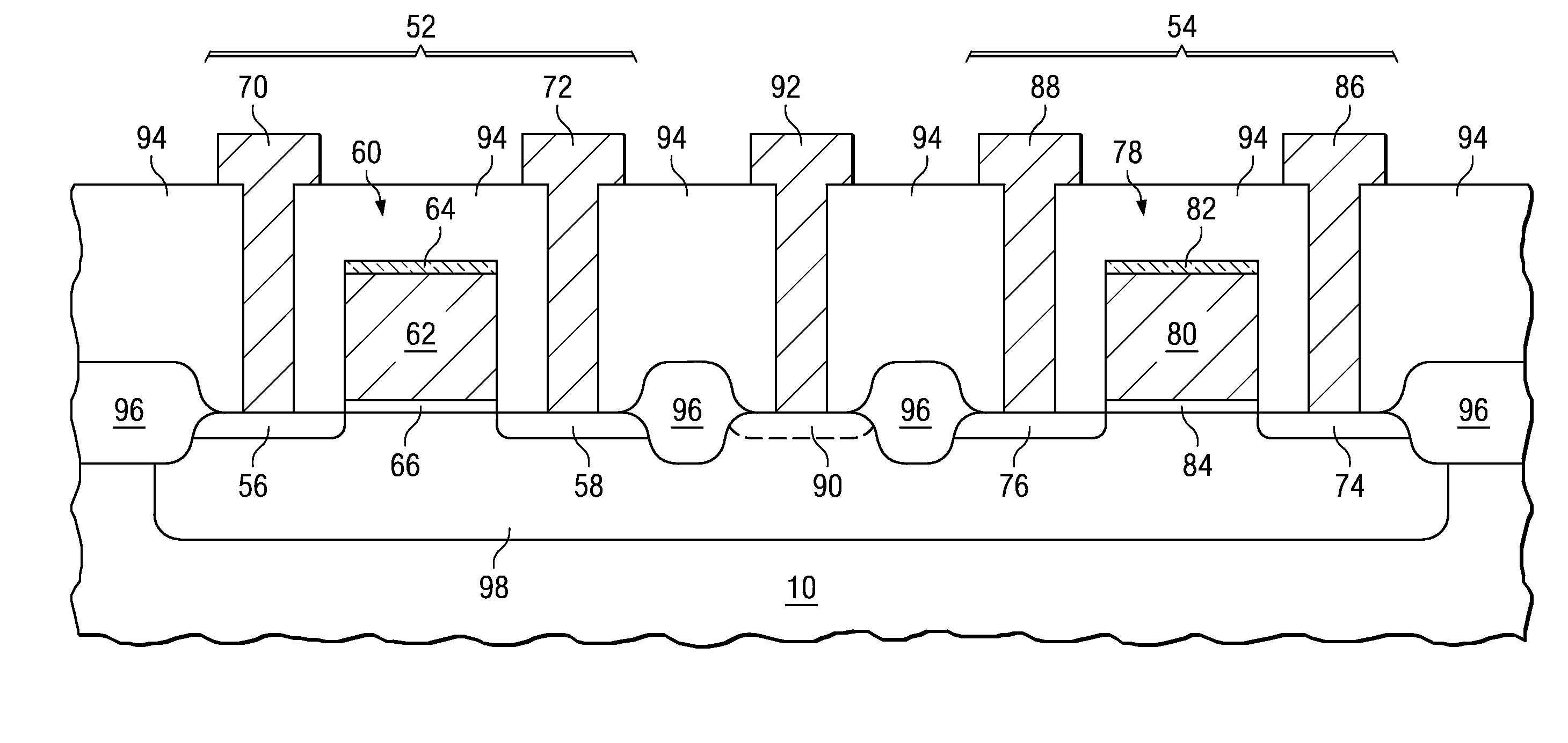
[0009]One exemplary embodiment of a test structure for a semiconductor device includes at least a portion of a semiconductor wafer and a metal oxide semiconductor (MOS) device having a source, a drain, and a transistor gate. The test structure further includes a one time programmable floating gate transistor having a source, a drain, and a floating gate. Also included are various probe contacts, with a first probe contact electrically coupled with the sources of both the MOS device and the floating gate device, a second probe contact electrically coupled with the drain of the MOS device, and a third probe contact electrically coupled with the transistor gate of the MOS device. A fourth probe contact is electrically coupled with the drain of the floating gate transistor, and a fifth probe contact is electrically coupled with the semiconductor wafer.

[0010]Further described is a method for testing a semiconductor device, including providing a test structure having a MOS transistor and ...


PUM


Abstract

A test structure which can be used to detect residual conductive material such as polysilicon which can result from an under etch comprises a PMOS transistor and an OTP EPROM floating gate device. By testing the devices using different testing parameters, it can be determined whether residual conductive material remains subsequent to an etch, and where the residual conductive material is located on the device. A method for testing a semiconductor device using the test structure is also described.

Description

FIELD OF THE INVENTION[0001]This invention relates to the field of semiconductor device processing. More particularly, a method and structure which can be used to detect conductive residues is disclosed.BACKGROUND OF THE INVENTION[0002]During semiconductor device processing, various structures are formed using a variety of materials and technologies. P-channel metal oxide semiconductor (PMOS) devices, n-channel MOS (NMOS) devices, erasable programmable read-only memory (EPROM) devices, resistors, capacitors, etc. can be formed using known processing techniques.[0003]Photolithography is commonly used to form structures such as polysilicon transistor gates (control gates), for example gates for one time programmable (OTP) EPROMs and p-channel and n-channel MOS devices. Due to the very large number of these structures formed with a typical memory device, even a minimal decrease in the width of the control gate can significantly decrease the size of the completed device. Miniaturization...

Claims


Application Information

Patent Timeline
Patent Type & Authority Applications(United States)
IPC IPC(8): G01R31/26H01L23/58
CPCG01R31/2831G11C16/04G11C29/04G11C2029/0403H01L22/34
Inventor WU, XIAOJUMITROS, JOZEF CZESLAW
Owner TEXAS INSTR INC
Why Eureka
Try Eureka