Check patentability & draft patents in minutes with Patsnap Eureka AI!

Clock generation devices and methods

a clock generation and clock technology, applied in the direction of digital transmission, pulse automatic control, transmission, etc., can solve the problems of difficult control of the frequency of the resonator, crystal cost increase, and data eventually not meeting the specification

Active Publication Date: 2009-07-02
MEDIATEK INC
View PDF32 Cites 5 Cited by
  • Summary
  • Abstract
  • Description
  • Claims
  • Application Information

AI Technical Summary

Benefits of technology

[0007]Thus, it is desired to provide a clock generation device for a transmitter, which uses a low-cost reference clock generator and generates a clock signal whose frequency conforms to the frequency ppm range defined by a specification, so that the output data of the transmitter meet the specification.

Problems solved by technology

If the frequency of the reference clock signal CLKref does not conform to the defined frequency ppm range of the specification, the frequency of the clock signal TXCLK is hard to conform to the defined frequency ppm range, so that the transmitted data eventually does not meet the specification.
A crystal has a concentrated frequency ppm range; however, compared with a resonator, the crystal has a higher cost.
In the other hand, it is difficult controlled the frequency of the resonator, which is a cheaper choice of the clock generator 12, to conform to a frequency ppm range defined by a required specification.

Method used


Image

  • Clock generation devices and methods
  • Clock generation devices and methods
  • Clock generation devices and methods

Examples


Embodiment Construction

[0018]The following description is of the best-contemplated mode of carrying out the invention. This description is made for the purpose of illustrating the general principles of the invention and should not be taken in a limiting sense. The scope of the invention is best determined by reference to the appended claims.

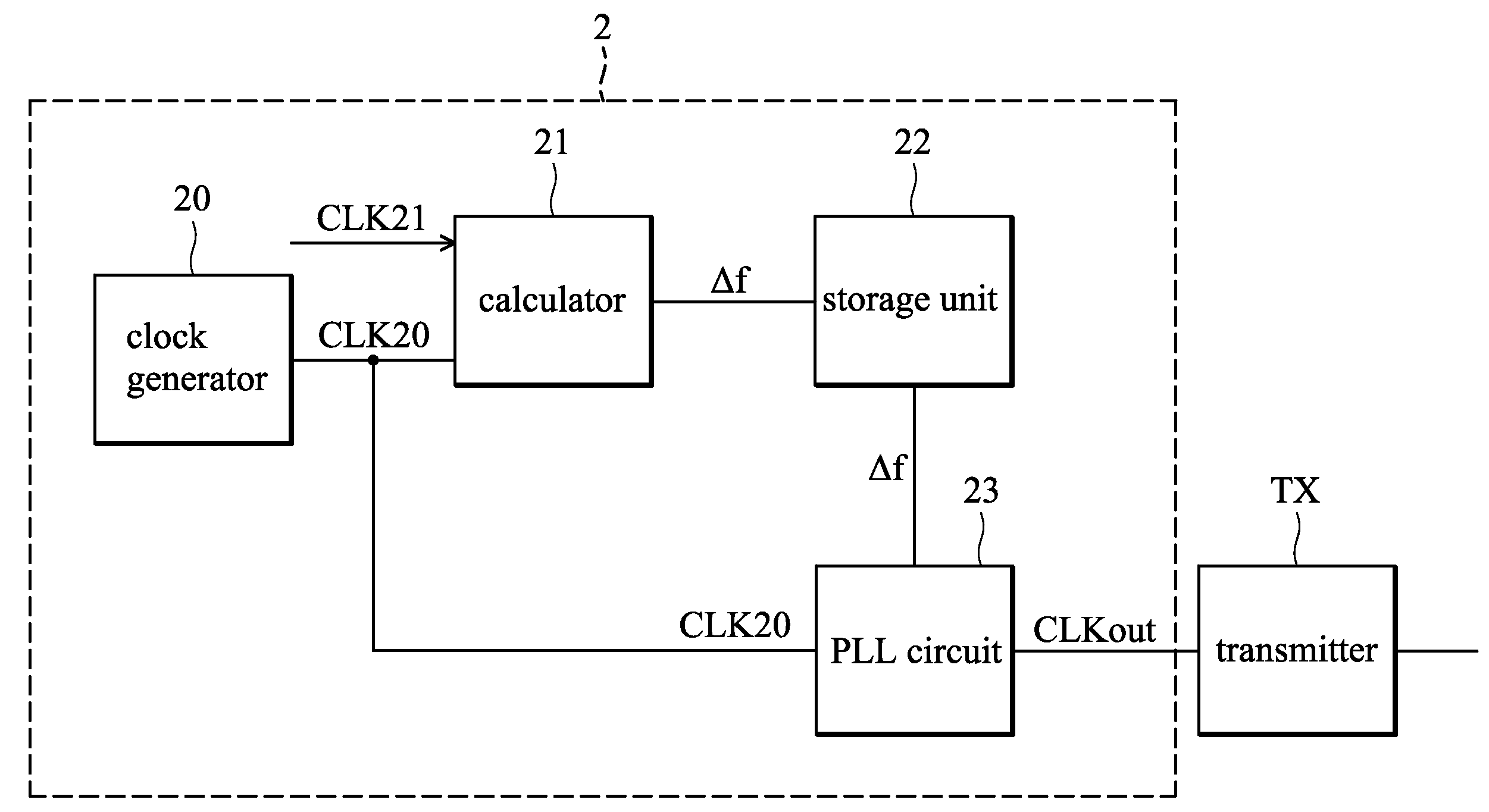
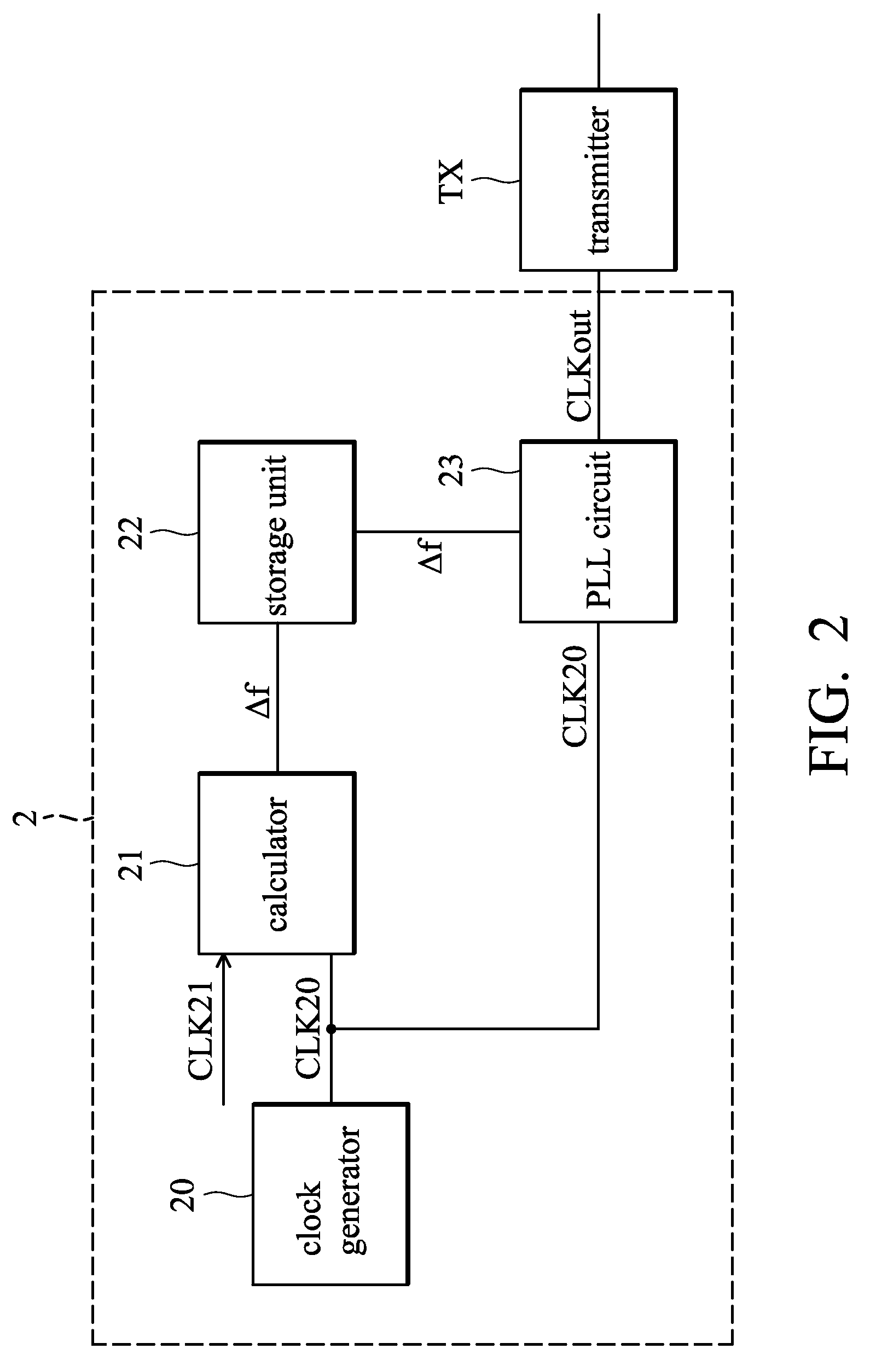
[0019]The embodiments of the invention provide clock generation devices for transmitters. The transmitter is arranged to transmit data according to an output clock signal, and the frequency of the output clock signal is expected to conform to a frequency ppm range defined by a required specification. The clock generation device comprises a clock generator, a calculator, and a phase lock loop (PLL) circuit. The clock generator generates a first clock signal which may have an incorrect frequency. The PLL circuit is arranged to generate the output clock signal according to a reference clock signal related to the first clock signal. The calculator calculates a frequency di...


PUM


Abstract

A clock generation device provided for a transmitter is provided and comprises a clock generator, a calculator and a first phase locked loop (PLL) circuit. The clock generator generates a first clock signal. The calculator calculates a frequency difference between the first and second clock signals. The first PLL circuit generates an output clock signal according to a first reference clock signal related to the first clock signal, and a frequency of the output clock signal is changed according to the frequency difference. The transmitter transmits data according to the output clock signal.

Description

CROSS REFERENCE TO RELATED APPLICATIONS[0001]The present application claims the benefit of U.S. provisional application entitled “FLOW AND CIRCUIT FOR FREQUENCY CALIBRATION”, Ser. No. 61 / 017,186, filed Dec. 28, 2007.BACKGROUND OF THE INVENTION[0002]1. Field of the Invention[0003]The invention relates to a clock generation device, and more particularly to a clock generation device whose output clock signal can be adjusted to be within a frequency ppm range defined by a specification.[0004]2. Description of the Related Art[0005]FIG. 1 shows a conventional transmission device 1, which comprises a transmitter 10, a phase locked loop (PLL) circuit 11, and a clock generator 12. The clock generator 12 generates a reference clock signal CLKref, which is provided to the PLL circuit 11. The PLL circuit 11 generates a clock signal TXCLK according to the reference clock signal CLKref and provides the clock signal TXCLK to the transmitter 10, and the transmitter 10 transmits data with the clock ...

Claims


Application Information

Patent Timeline
Patent Type & Authority Applications(United States)
IPC IPC(8): H04L7/00
CPCH03L7/07
Inventor CHAO, KUAN-HUALIU, CHUANHSU, TSE-HSIANG
Owner MEDIATEK INC
Features
  • R&D
  • Intellectual Property
  • Life Sciences
  • Materials
  • Tech Scout
  • Unparalleled Data Quality
  • Higher Quality Content
  • 60% Fewer Hallucinations
Learn More