Hearing device comprising a mould and an output module

a technology of output module and hearing device, which is applied in the direction of hearing aid vents, deaf-aid sets, electric devices, etc., can solve the problems of reducing the flexibility of hearing aid manufacturing, undesired feedback effect, and reducing comfort for users, so as to increase the feedback margin, and reduce the occlusion

Active Publication Date: 2009-07-02
OTICON
View PDF6 Cites 15 Cited by
  • Summary
  • Abstract
  • Description
  • Claims
  • Application Information

AI Technical Summary

Benefits of technology

[0019]The plurality of venting channels leads to a compact and space-saving arrangement of the hearing device. For a given optimal cross-sectional area of one tubular vent, the corresponding cross-sectional area distributed on a number of (necessarily smaller) vent channels provides substantially the same effect at relatively low frequencies (e.g. lower than 2 kHz), but such an arrangement has a larger acoustical attenuation at relatively higher frequencies (e.g. larger than 2 kHz). The insertion of a porous material into the venting channels (over a part or all of the longitudinal extension of the vent) provides an additional possibility to control the acoustic attenuation of a venting channel of a given cross-sectional area and longitudinal extension. In an embodiment, a specific cross-sectional area of a single, air-filled tubular vent to provide an intended reduction of the occlusion effect is determined (for a given ear canal and enclosed volume). By design of a ‘distributed’ vent with the same (total) cross-sectional area, the resulting effect on occlusion is maintained (mainly determined by the low-frequency part of the signal), but with an increased feedback margin at higher frequencies (e.g. >2 kHz) due to the increased attenuation at these frequencies. By using a number of relatively smaller vents (with or without porous damping material in some or all of the vents over a part or its full length), and placing the vents close to the receiver outlet in the ear (as is ensured by the present construction of the output module and the location of the venting channels at the interface between the output module and the mould), a well-balanced condition is provided resulting in an intended reduction of the occlusion effect and an improved feed-back condition (reduced feedback).
[0020]The cross-sectional shape of an individual venting channel can have any appropriate form, e.g. rectangular (such as square) or elliptical (such as circular) of triangular (e.g. a groove). Typically, the cross-sectional shapes of the number of vents will be identical. They may however be different, e.g. depending on the needed attenuation, particular geometrical constraints, etc. In an embodiment, the cross-sectional shape of a vent is identical over its longitudinal extension. This need not be the case, however. In an embodiment, the cross-sectional form and / or area changes along the length of the vent, e.g. increasing from one end to the other. In an embodiment, the vent has a larger cross-sectional area at the end facing the enclosed volume (cf. B in FIG. 1) than at the end facing the outside (cf. A in FIG. 1), thereby providing an improved ‘collection’ of sound vibrations in the enclosed volume.
[0021]In a further aspect, an ear-located part of a hearing device is provided, the ear-located part comprising a) a mould for being inserted in a user's ear canal, the mould being arranged to have an opening with an inner surface, and b) an output module comprising a receiver for providing an acoustic output and being enclosed in a housing having an outer surface, and wherein the dimensions and form of the outer surface of the output module, the opening and the inner surface of the mould being adapted to allow the output module to be mounted in the opening, at least over a part of their common spatial extension, and wherein at least one venting channel is arranged between the inner surface of the mould and an outer surface of the output module. In an embodiment, the input transducer (input unit) and the signal processing unit (control unit) are located in the mould.
[0022]It is intended that the features described above for a hearing device, in the detailed description and in the claims—where appropriate—can be freely combined with the ear-located part of a hearing aid.
[0023]In a further aspect, a hearing device is provided, the hearing device comprising a) a NITE-part adapted to be located at or behind the ear or other places on the body, b) an ITE-part adapted for being at least partially located in the ear canal of a user, the hearing device comprising an input transducer for converting an input sound to an electrical input signal, a signal processing unit for providing a processed output signal applying a frequency dependent gain to the electric input signal according to a user's needs and an output transducer for converting the processed output signal to an output sound for being presented to the user. The ITE-part comprises an ear-located part of a hearing device as described above. The ear-located part (and thus the ITE-part) comprises a mould and an output module. In an embodiment, the input transducer and the signal processing unit are located in the NITE-part and the output transducer is located in the output module. In an embodiment, the only electronic component contained in the output module is the receiver (speaker). In an embodiment, the only electronic components contained in the output module are a wireless receiver, possibly comprising an amplifier of the received signal to adapt its level to the receiver (speaker) in question, and the receiver (speaker). In an embodiment, the NITE-part is a BTE part adapted for being located at or behind the ear (pinna). In an embodiment, the NITE part is a body worn part, e.g. worn around the neck or, in a pocket or the like.
[0024]The foregoing and other objects, features and advantages of the present invention will become more apparent from the following detail the description in conjunction with the corresponding drawings referring to embodiments and developments of the present invention.

Problems solved by technology

Many of today's hearing aids comprising an ear mould or the like include a venting channel to provide suitable ventilation and to avoid the undesired occlusion effect, which reduces comfort for the user.
In other words, an otherwise desirable large-diameter ear canal more efficiently propagates the amplified higher frequencies of the ear and might thus create an undesired feedback effect.
This reduces flexibility when manufacturing the hearing aid since a certain space of the hearing aid mould is occupied by the venting channel.

Method used


Image

  • Hearing device comprising a mould and an output module
  • Hearing device comprising a mould and an output module
  • Hearing device comprising a mould and an output module

Examples


first embodiment

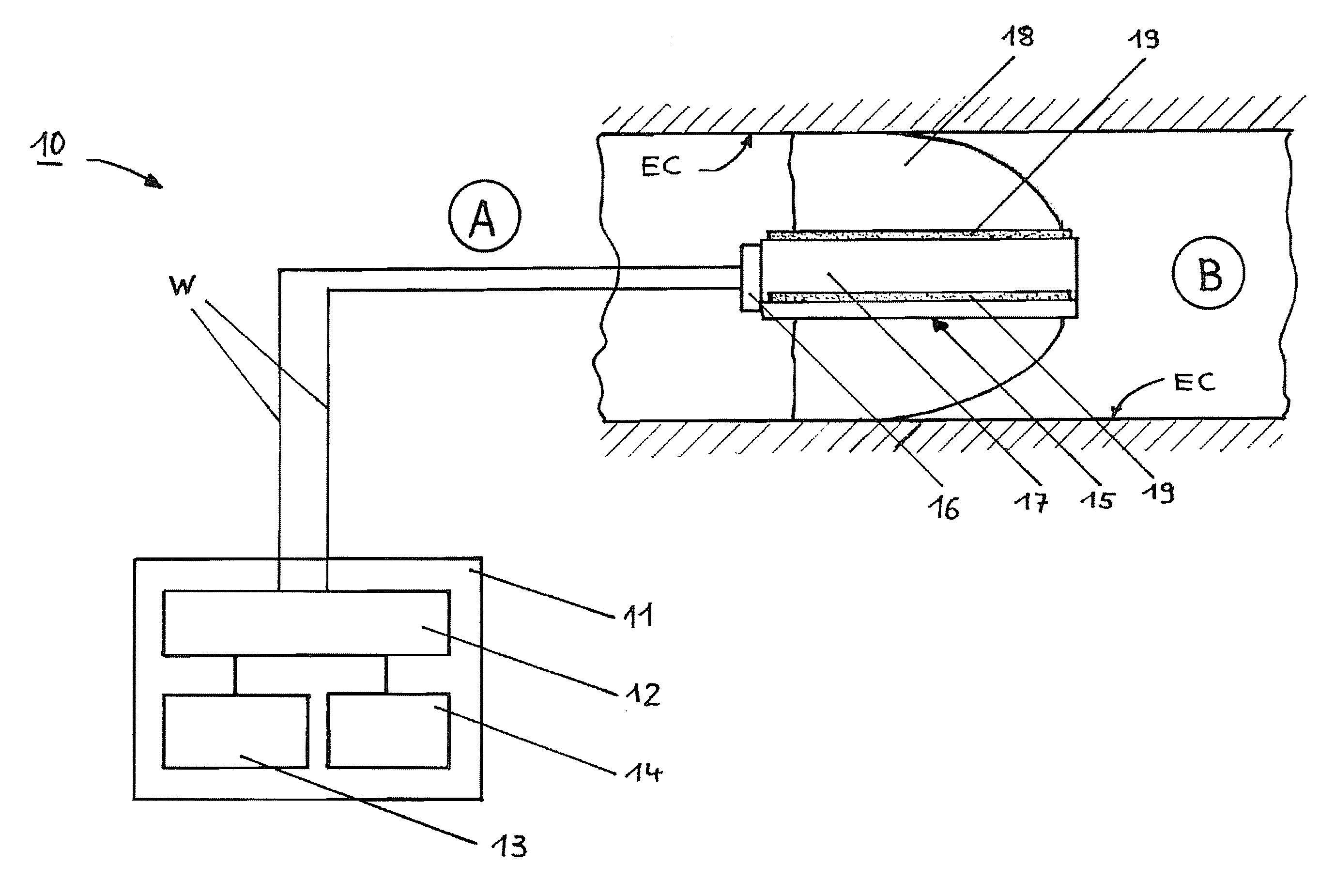
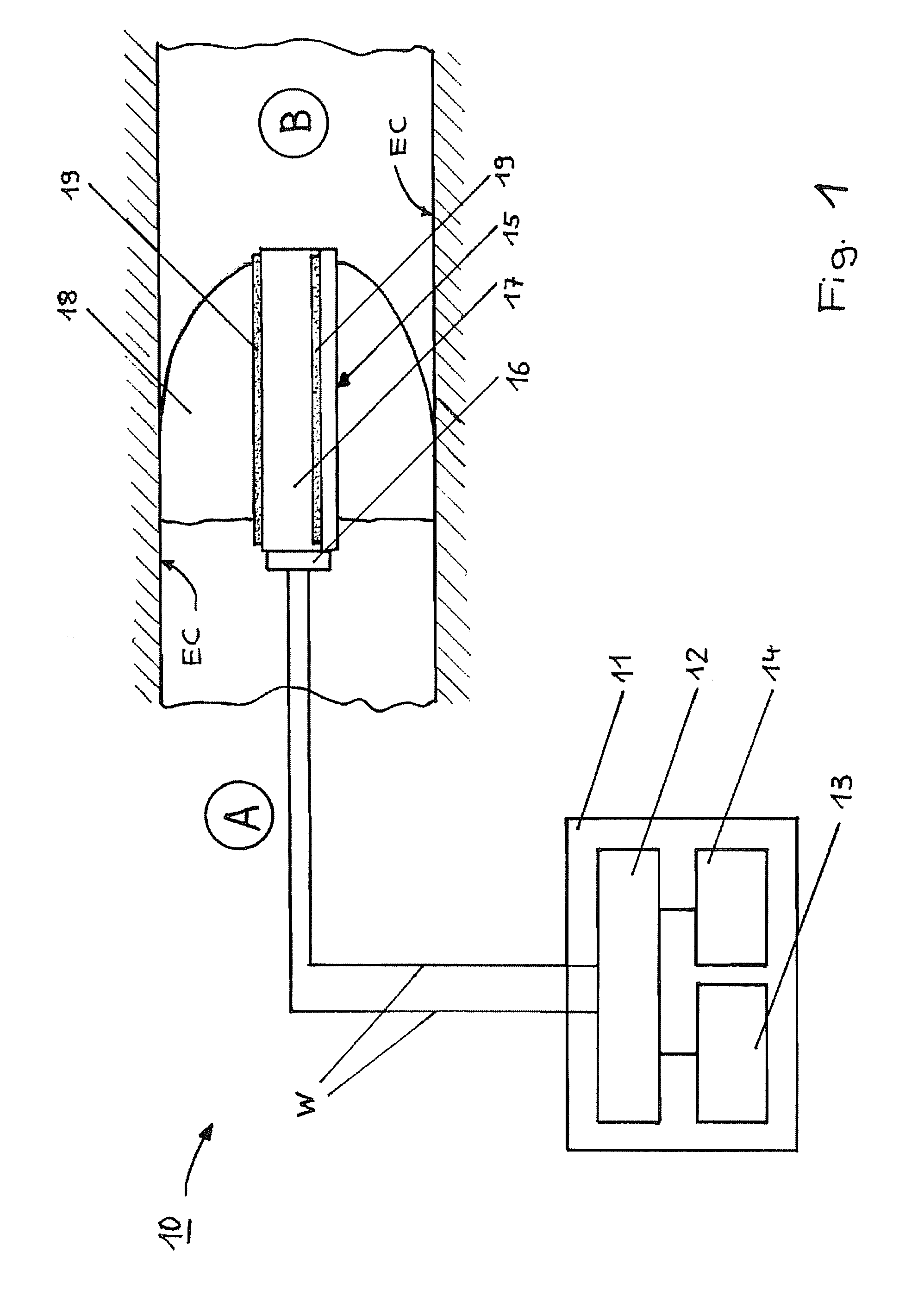
[0035]The present invention is described in the following in conjunction with the schematic diagram of FIG. 1 showing an overall view (cross-sectional view in part) of the structure and arrangement of a hearing device 10 according to the first embodiment of the present invention. The hearing device 10 comprises three separate physical bodies, 1) circuitry unit 11, 2) mould 18 and 3) output module 15 mounted in a through-going opening of the mould, the circuitry unit and the output module being electrically connected. The circuitry unit 11 can e.g. form part of a module located behind the ear of a user.

[0036]According to the representation shown in FIG. 1, the hearing device 10 comprises a casing, (shell) at least enclosing electronic circuitry providing a signal processing unit of the hearing device. The electronic circuitry comprises a circuitry unit 11 comprising a central control unit 12 (controller) that controls the hearing device 10 to be worn by the user. The central control ...

second embodiment

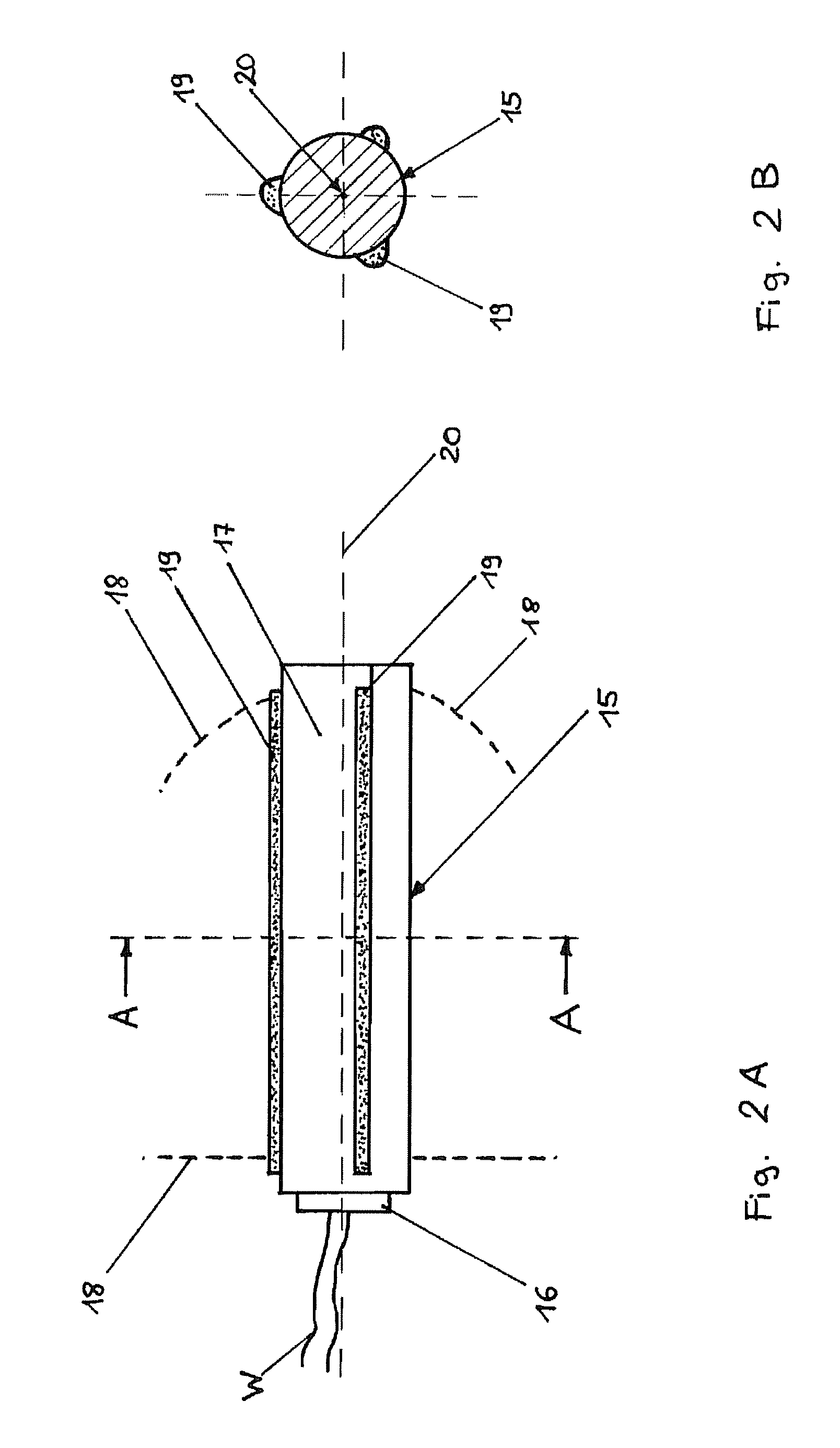
[0077]Based on the representation of FIGS. 4A and 4B a second embodiment of the present invention is described in the following.

[0078]Elements and means shown in FIGS. 4A and 4B which have already been described in conjunction with the first embodiment and which are shown in any of the preceding Figures (FIGS. 1 to 3) and which have the same function are provided with the same reference number, and a further detailed explanation thereof is omitted.

[0079]FIG. 4A, which is a cross-sectional view, shows the arrangement of an output module 15 in a mould 18, the output module including a housing 17 in which a receiver is accommodated. Electric wires W provide a connection of the output module to a circuitry unit 11 (not shown in FIG. 4, see FIG. 1). The circuitry unit 11 according to the second embodiment has the same function as that of the first embodiment, and a further description is therefore omitted.

[0080]FIG. 4A further shows that the output module 15 is inserted into a portion (w...


PUM


Abstract

A hearing device having a circuitry unit which is adapted for processing sound signals and converting the processed sound signals into corresponding electrical signals. An output module is provided for receiving the electric signals after processing by the circuitry unit. The output module defines an outer surface. At least one venting channel is arranged adjacent to the outer surface of the output module of the hearing device. The hearing device may also have a mould, which is adapted to receive the output module in a through going opening. The at least one venting channel is arranged at the interface between the mould and the output module and advantageously provides a pressure balance in the user's ear canal to minimize occlusion. An ITE-part of a hearing device is furthermore provided.

Description

FIELD OF THE INVENTION[0001]The present invention refers to a hearing device comprising an ear mould, and specifically to a hearing device having a venting channel arrangement.BACKGROUND OF THE INVENTION[0002]Many of today's hearing aids comprising an ear mould or the like include a venting channel to provide suitable ventilation and to avoid the undesired occlusion effect, which reduces comfort for the user. The occlusion effect is caused when a hearing aid (here termed hearing device) or any part thereof is inserted into the user's ear canal and thereby defines a sealed or closed portion of the user's ear canal between the hearing aid or the part thereof and the user's ear drum. For example, in CIC (completely in the ear canal) / ITC (in the canal) / ITE (in the ear) hearing aids a blocking of the ear canal of the user wearing the hearing aid is possible, and this causes a build-up of a low frequency sound pressure, resulting in the above-mentioned and well-known occlusion effect.[000...

Claims


Application Information

Patent Timeline
Patent Type & Authority Applications(United States)
IPC IPC(8): H04R25/00
CPCH04R25/652H04R25/658H04R2460/11
Inventor RASMUSSEN, KARSTEN BOPETERSEN, SVEND OSCAR
Owner OTICON
Why Eureka
Try Eureka