Apparatus and method for fan auto-detection

a technology of automatic detection and fan, applied in the direction of motor/generator/converter stopper, dynamo-electric converter control, instruments, etc., can solve the problem that the heat produced by memory cards and other components in electronic devices, e.g., computers, has increased in working frequency and power consumption, and may not be sufficient for some electronic devices

Active Publication Date: 2009-07-02
NUVOTON
View PDF6 Cites 26 Cited by
  • Summary
  • Abstract
  • Description
  • Claims
  • Application Information

AI Technical Summary

Benefits of technology

[0009]In accordance with the invention, there is provided an apparatus for detecting a type of fan and controlling the fan, the fan providing during operation a tachometer signal indicating a speed of the fan, the apparatus comprising: a direct current (DC) generator for coupling to the fan and configured to provide a first voltage to the fan; a resistor for providing, while the DC generator provides the first voltage, a sensed voltage relating to the type of the fan, wherein the resistor is connected to a reference voltage and for coupling to a pulse-width modulation (PWM) control terminal of the fan; an input judgment component coupled to the resistor to receive the sensed v...

Problems solved by technology

Due to recent technology developments, processors, memory cards, and other components in electronic devices, e.g., computers, have increased in working frequency and power consumption.
As a result, the amount of heat produced by these components as a side effect of normal operation may have...

Method used


Image

  • Apparatus and method for fan auto-detection
  • Apparatus and method for fan auto-detection
  • Apparatus and method for fan auto-detection

Examples


Embodiment Construction

[0019]Reference will now be made in detail to exemplary embodiments, examples of which are illustrated in the accompanying drawings. The following description refers to the accompanying drawings in which the same numbers in different drawings represent the same or similar elements unless otherwise represented. The implementations set forth in the following description of exemplary embodiments consistent with the present invention do not represent all implementations consistent with the claimed invention. Instead, they are merely examples of systems and methods consistent with aspects related to the invention as recited in the appended claims.

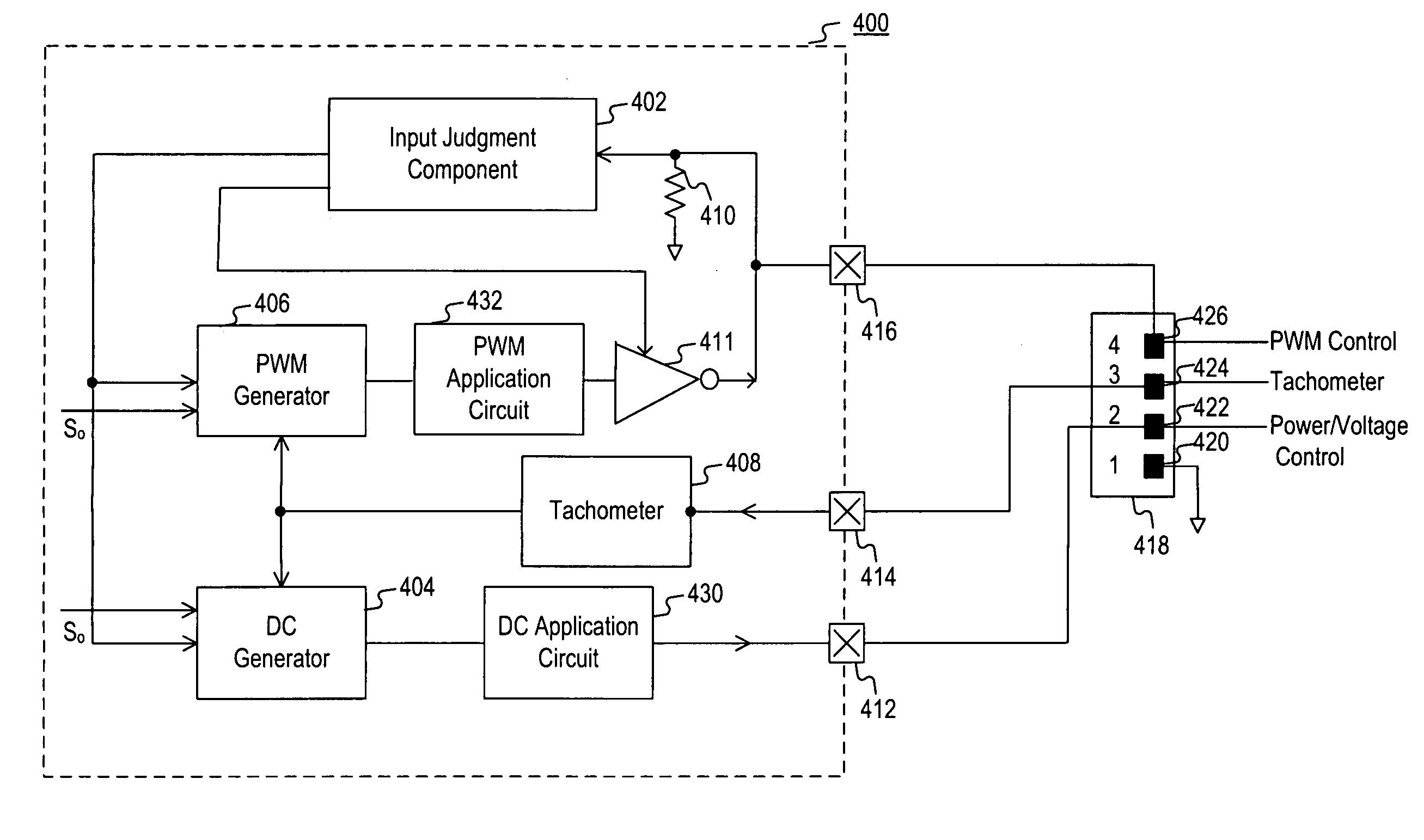
[0020]In embodiments consistent with the present invention, there is provided an apparatus for automatic detection of a type of fan and appropriately control the fan according to the fan type. Such automatic detection is also referred to herein as “auto-detect” or “auto-detection.” The apparatus may be incorporated into an electronic device, e.g...


PUM


Abstract

An apparatus for detecting a type of fan and controlling the fan, the fan providing during operation a tachometer signal indicating a speed of the fan, the apparatus includes: a direct current (DC) generator for coupling to the fan and configured to provide a first voltage to the fan; a resistor for providing, while the DC generator provides the first voltage, a sensed voltage relating to the type of the fan, wherein the resistor is connected to a reference voltage and for coupling to a pulse-width modulation (PWM) control terminal of the fan; an input judgment component coupled to the resistor to receive the sensed voltage, the input judgment component being configured to determine whether the fan is a 4-wire PWM fan with an internal pull-up resistor based on the sensed voltage and to provide a judgment signal indicating the determination; a PWM generator coupled to the input judgment component to receive the judgment signal, the PWM generator being configured to provide to the fan a PWM control signal to control the fan if the judgment signal indicates that the fan is the 4-wire PWM fan with an internal pull-up resistor; and a tachometer coupled to the DC generator and the PWM generator, the tachometer being configured to receive the tachometer signal to detect a change in the speed of the fan.

Description

FIELD OF THE INVENTION[0001]This invention pertains in general to an apparatus and method for heat dissipation and, more particularly, to an apparatus and method for fan auto-detection and control.BACKGROUND OF THE INVENTION[0002]Due to recent technology developments, processors, memory cards, and other components in electronic devices, e.g., computers, have increased in working frequency and power consumption. As a result, the amount of heat produced by these components as a side effect of normal operation may have also increased. To prevent possible overheating of such components, which may lead to malfunction and damage of the electronic devices, temperatures of those components usually need to be monitored, and kept within a reasonable range by dissipation of heat generated by those components, i.e., the components to be cooled. Dissipation of heat generated by those components may also improve their reliability.[0003]Heat dissipation techniques for electronic devices may includ...

Claims


Application Information

Patent Timeline
IPC IPC(8): H02P7/29
CPCH05K7/20209Y10S388/934
Inventor HUANG, SHIH-FENGLU, CHIA-CHINGHUNG, MING-CHE
Owner NUVOTON
Why Eureka
Try Eureka