Wind turbine blade with sufficiently high strength and light weight

Active Publication Date: 2009-07-02
MITSUBISHI HEAVY IND LTD
View PDF23 Cites 59 Cited by
  • Summary
  • Abstract
  • Description
  • Claims
  • Application Information

AI Technical Summary

Benefits of technology

[0008]Therefore, an object of the present invention is to provide a wind turb

Problems solved by technology

However, the weight increase accompanied by the strength enhancement causes a mechanical load to be applied to the structure supporting wind turbine blades (for example, a nacelle and a tower).
For example, a wind turbine blade having a high strength and also an exces

Method used


Image

  • Wind turbine blade with sufficiently high strength and light weight
  • Wind turbine blade with sufficiently high strength and light weight
  • Wind turbine blade with sufficiently high strength and light weight

Examples


Example

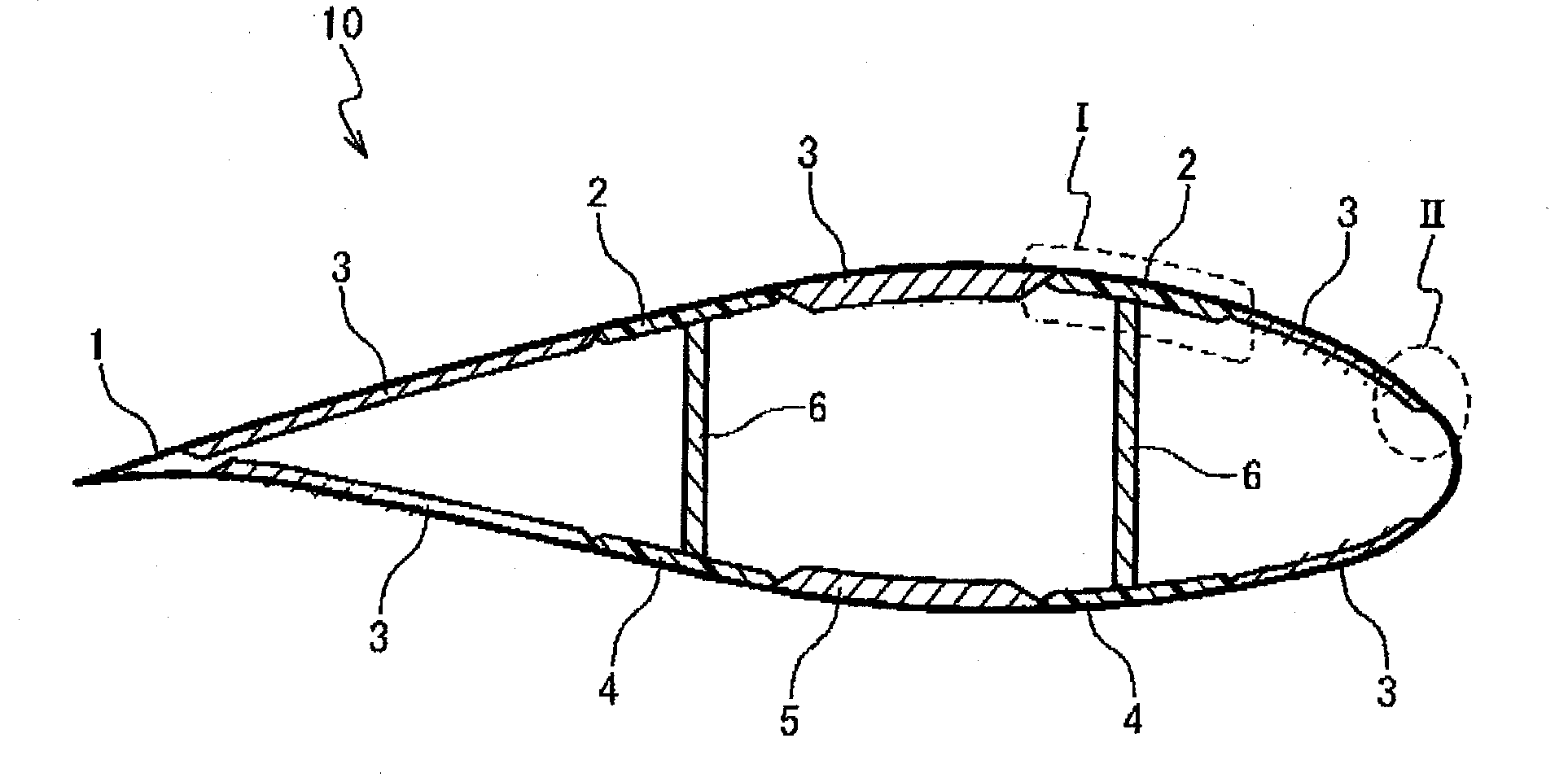
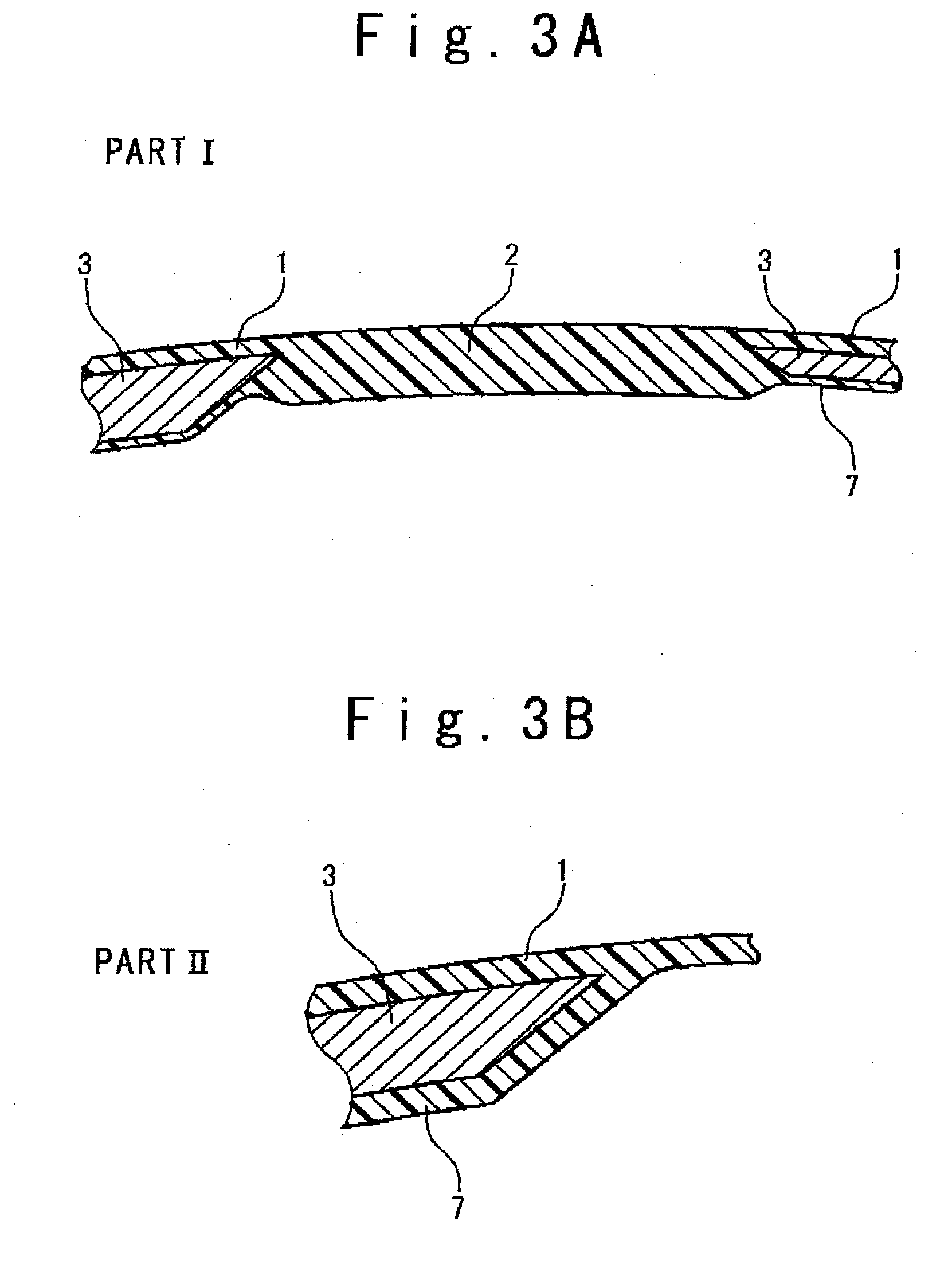
[0040]FIG. 1 is a cross sectional view showing the structure of a wind turbine blade 10 in one embodiment of the present invention. The wind turbine blade 10 includes an outer skin layer 1, main structural members 2 and 4, lightweight core members 3 and 5, and beam members 6.

[0041]The outer skin layer 1 is used for providing the blade profile of the wind turbine blade 10. The outer skin layer 1 is formed of fiber-reinforced plastics (FRP) such as carbon fiber reinforced plastics (CFRP) and grass fiber reinforced plastics (GFRP).

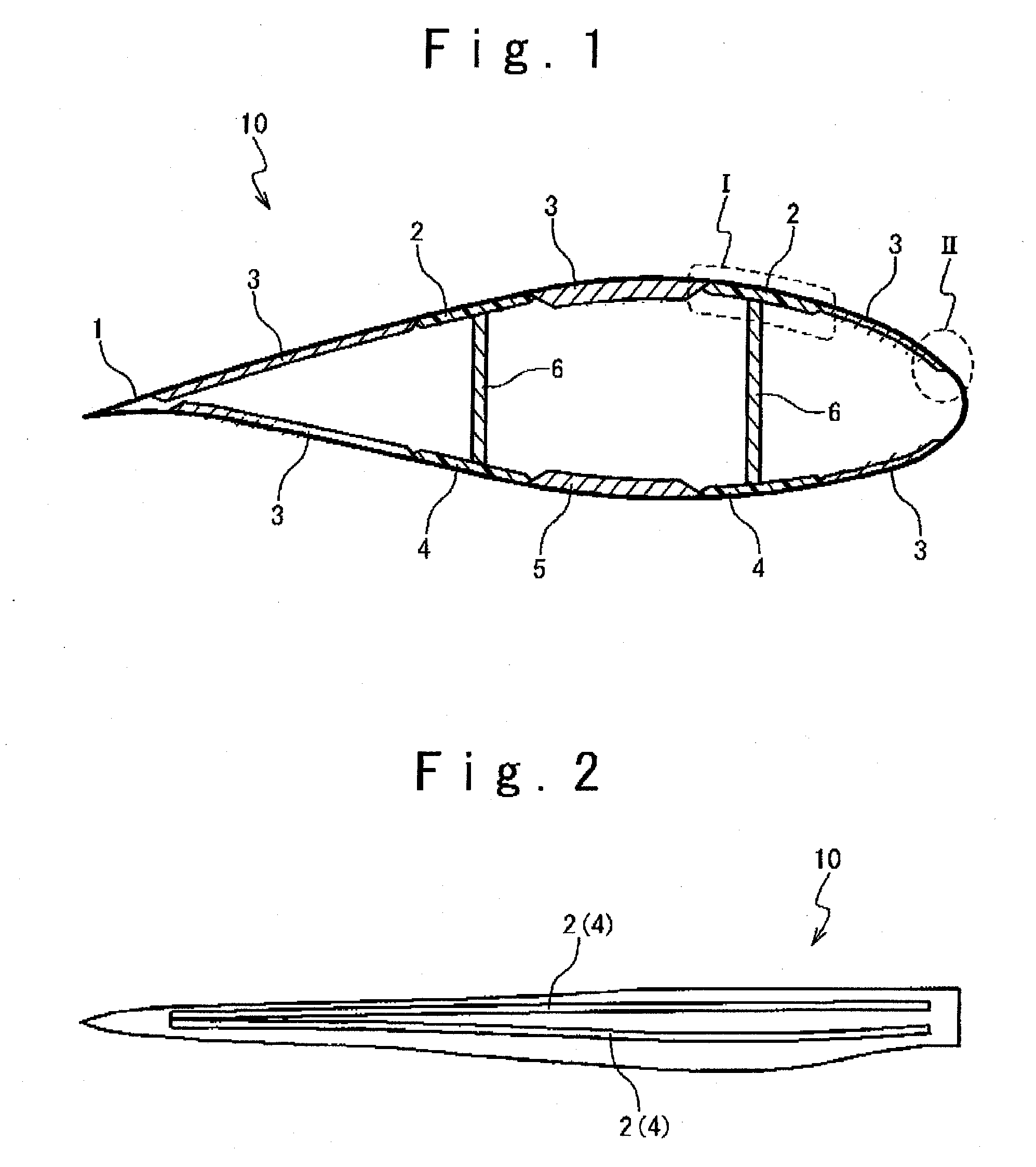
[0042]The main structural members 2 and 4 are structural bodies for mainly ensuring the strength of the wind turbine blade 10. The main structural members 2 are arranged on the dorsal side of the wind turbine blade 10, and the main structural members 4 are formed on the ventral side of the wind turbine blade 10. As shown in FIG. 2, the main structural members 2 are provided so as to extend in the blade length direction. It should be noted that multiple main s...


PUM


Abstract

A wind turbine blade is provided with an outer skin layer formed of fiber-reinforced plastic, and a plurality of main structural members formed of fiber-reinforced plastic integrally with the outer skin layer to extend in a blade length direction. The main structural members include a plurality of main dorsal structural members positioned on a dorsal side of the wind turbine blade, and a plurality of main ventral structural members positioned on a ventral side of the wind turbine blade.

Description

BACKGROUND OF THE INVENTION[0001]1. Field of the Invention[0002]The present invention relates to a wind turbine blade, and especially relates to a wind turbine blade preferably used for wind power generation and to a manufacture method thereof.[0003]2. Description of the Related Art[0004]One property required for wind turbine blades is lightweight with sufficient strength. This is important especially to provide large and long wind turbine blades (for example, a length more than 20 meters). To increase the length of a wind turbine blade, the structural strength of the wind turbine blade is required to be sufficiently high. However, the weight increase accompanied by the strength enhancement causes a mechanical load to be applied to the structure supporting wind turbine blades (for example, a nacelle and a tower). For example, a wind turbine blade having a high strength and also an excessive weight cannot be actually employed for a wind turbine.[0005]The spar cap structure is a wind ...

Claims


Application Information

Patent Timeline
IPC IPC(8): F03D1/06F03D3/06
CPCF03D1/0675F05B2280/6003Y02E10/722Y02E10/721F05C2253/04Y02E10/72
Inventor KUROIWA, TAKAOHIRANO, TOSHIYUKINAKAMURA, NOBUYASU
Owner MITSUBISHI HEAVY IND LTD
Why Eureka
Try Eureka